De-icing system for an aircraft

a technology for aircraft and ice, which is applied in the direction of air-flow influencers, transportation and packaging, energy-efficient board measures, etc., can solve the problems of increasing the weight of the respective aircraft, affecting the flight safety of the aircraft, and the engine needs to make available bleed air and/or electric current, so as to reduce the number of cabin air outflow valves

Active Publication Date: 2011-02-10
AIRBUS OPERATIONS GMBH
View PDF14 Cites 21 Cited by
  • Summary
  • Abstract
  • Description
  • Claims
  • Application Information

AI Technical Summary

Benefits of technology

This in turn makes it possible to reduce the number of cabin air outfl

Problems solved by technology

The freezing or freeze-related seizing of flaps and other movable parts, as well as the formation of ice on the wing profile, significantly deteriorates the aerodynamic properties and increases the weight of the respective aircraft such that the in-flight formation of ice needs to be prevented and ice that has already formed on an aircraft situated on the ground needs to be removed.
One particular disadvantage of previously known de-icing methods is the fact that the engi

Method used


Image

  • De-icing system for an aircraft
  • De-icing system for an aircraft
  • De-icing system for an aircraft

Examples


Embodiment Construction

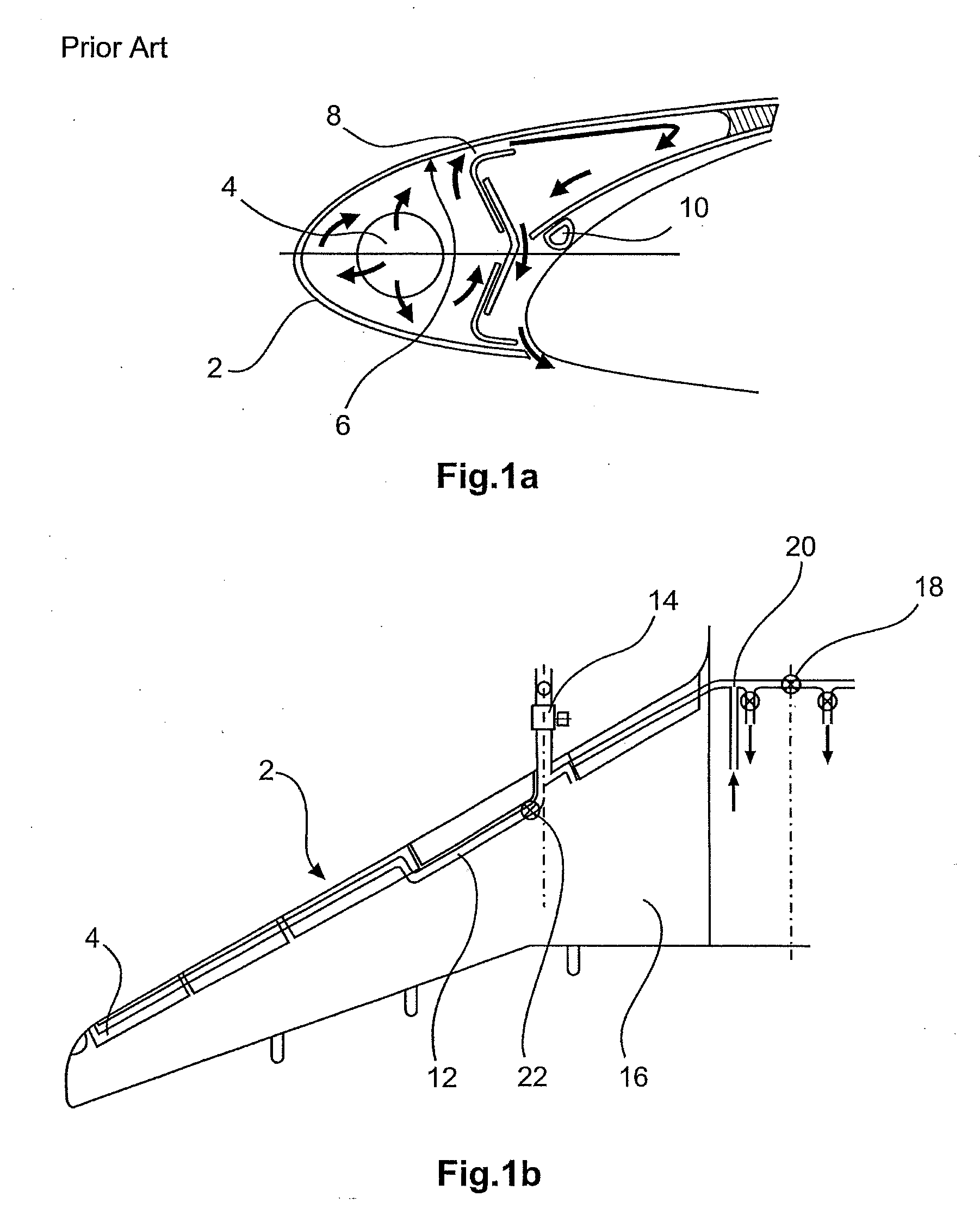
FIG. 1a schematically shows a widely used system for de-icing in aircraft wing according to the prior art. A perforated pipeline 4 (also referred to as “Piccolo tube”) is situated in a leading wing edge 2, wherein warm air is discharged from said pipeline toward the inner side 6 of the leading wing edge 2 in order to prevent an ice accumulation thereon due to the input of heat. In the example shown in FIG. 1a, the leading wing edge 2 consists of the leading edge of a leading wing edge flap (also referred to as “slat”). Within this leading wing edge flap, the warm air discharged toward the leading edge 2 can also flow into regions that are situated further toward the rear referred to the direction of flight and further toward the upper side of the wing and thusly keep mating seals 10 free of ice. If the warm air is discharged tangentially, the outflow is preferably realized behind the separation layer.

FIG. 1b elucidates the correlation between the perforated pipelines 4 and an air so...


PUM


Abstract

The invention pertains to a de-icing system for an aircraft with at least one heat source and at least one air delivery means for delivering air into regions of the aircraft to be de-iced. In comparison with the prior art, the invention is characterized in that the air delivery means is connected to an air-conditioning system of the aircraft for discharging air from the cabin of the aircraft via an air heating device, wherein the air heating device is connected to at least one heat source in order to heat the air from the cabin of the aircraft. The de-icing system according to the invention is able to realize a wing de-icing that not only fulfills an anti-icing function, but also a de-icing function on the ground without additional expenditure of energy. The function of the de-icing system according to the invention could also be advantageously supplemented by utilizing the cabin waste air for increasing the flow energy on the upper side of the wing in order to delay a change-over or separation of the boundary layer and to generally increase the lift or lower the resistance.

Description

FIELD OF THE INVENTIONThe invention pertains to a de-icing system for an aircraft with at least one air delivery means and a heat source.TECHNOLOGICAL BACKGROUND OF THE INVENTIONAircraft, in particular larger passenger aircraft, need to be de-iced during certain flight phases and on the ground for a number of reasons. The freezing or freeze-related seizing of flaps and other movable parts, as well as the formation of ice on the wing profile, significantly deteriorates the aerodynamic properties and increases the weight of the respective aircraft such that the in-flight formation of ice needs to be prevented and ice that has already formed on an aircraft situated on the ground needs to be removed. These two processes are usually referred to as “de-icing” (ice removal) and “anti-icing” (prevention of ice formation). Although the following description concerns, in particular, anti-icing, the invention is by no means restricted to anti-icing.Different variations of anti-icing systems ha...

Claims


Application Information

Patent Timeline
IPC IPC(8): B64D15/04B64C21/04B64D13/08
CPCB64C21/04B64D15/04B64D2013/0607B64D2013/0614Y02T90/36B64D2041/005Y02T50/166Y02T50/56B64D2013/0622Y02T50/10Y02T50/50Y02T90/40
Inventor STOLTE, RALF-HENNINGWOLLRAB, UWE
Owner AIRBUS OPERATIONS GMBH
Why Eureka
Try Eureka