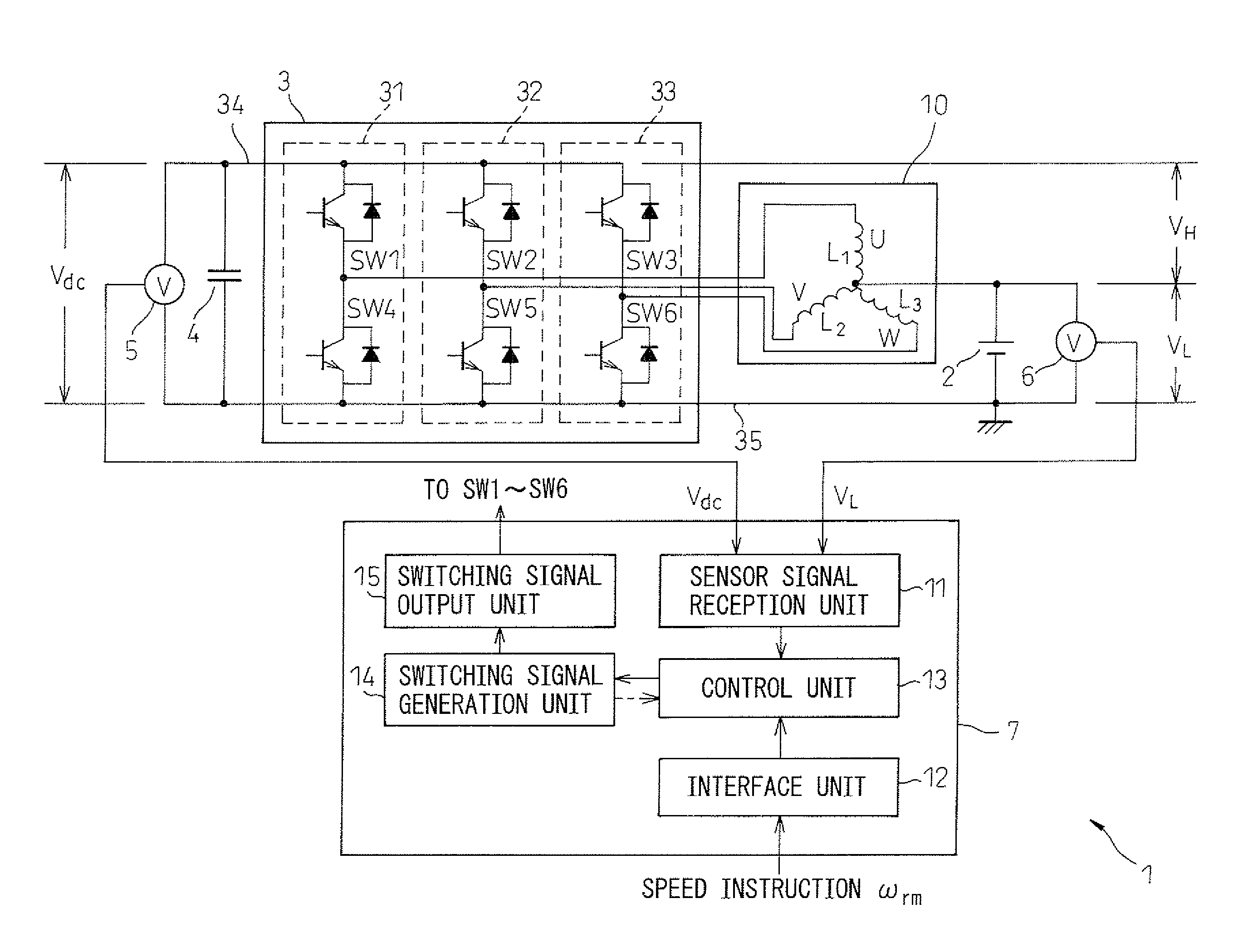
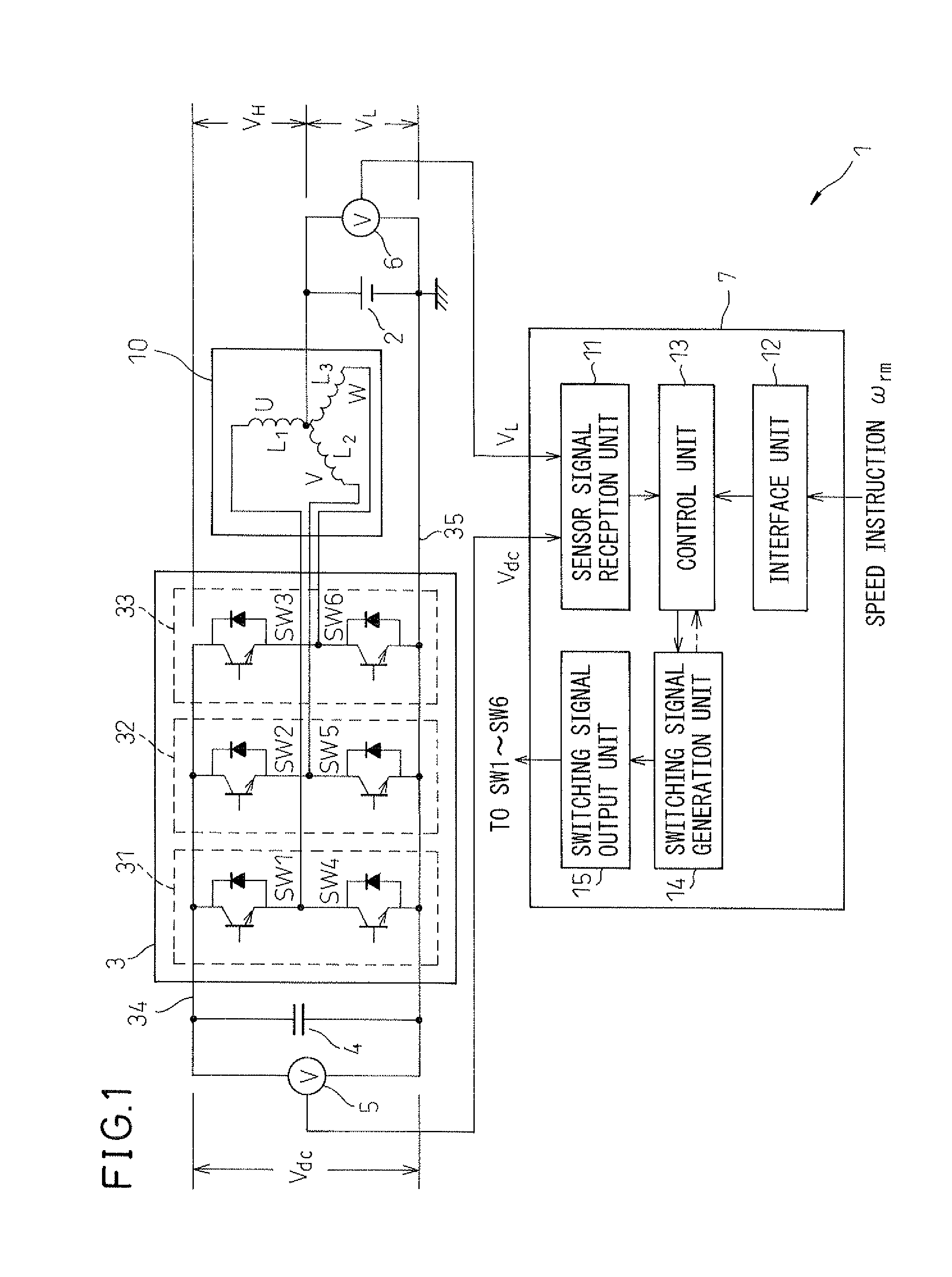
[0006]As one aspect of the present invention, there is provided an electric motor drive device which drives an AC electric motor including a plurality of coils connected in a star configuration. Such an electric motor drive device includes an inverter including a plurality of arms, each of the plurality of arms corresponding to any one of the plurality of coils of the AC electric motor and including a first switching device connected to a positive rail and a second switching device connected in series between the first switching devices and a negative rail, wherein, for each of the plurality of arms, the midpoint of the first switching device and second switching device is connected with one end of the corresponding coil of the AC electric motor; a
capacitor charged by a current supplied from a DC power supply supplying
DC voltage between a neutral point to which the coils of the AC electric motor are connected and a positive rail or negative rail of the inverter and passing through the inverter; and a
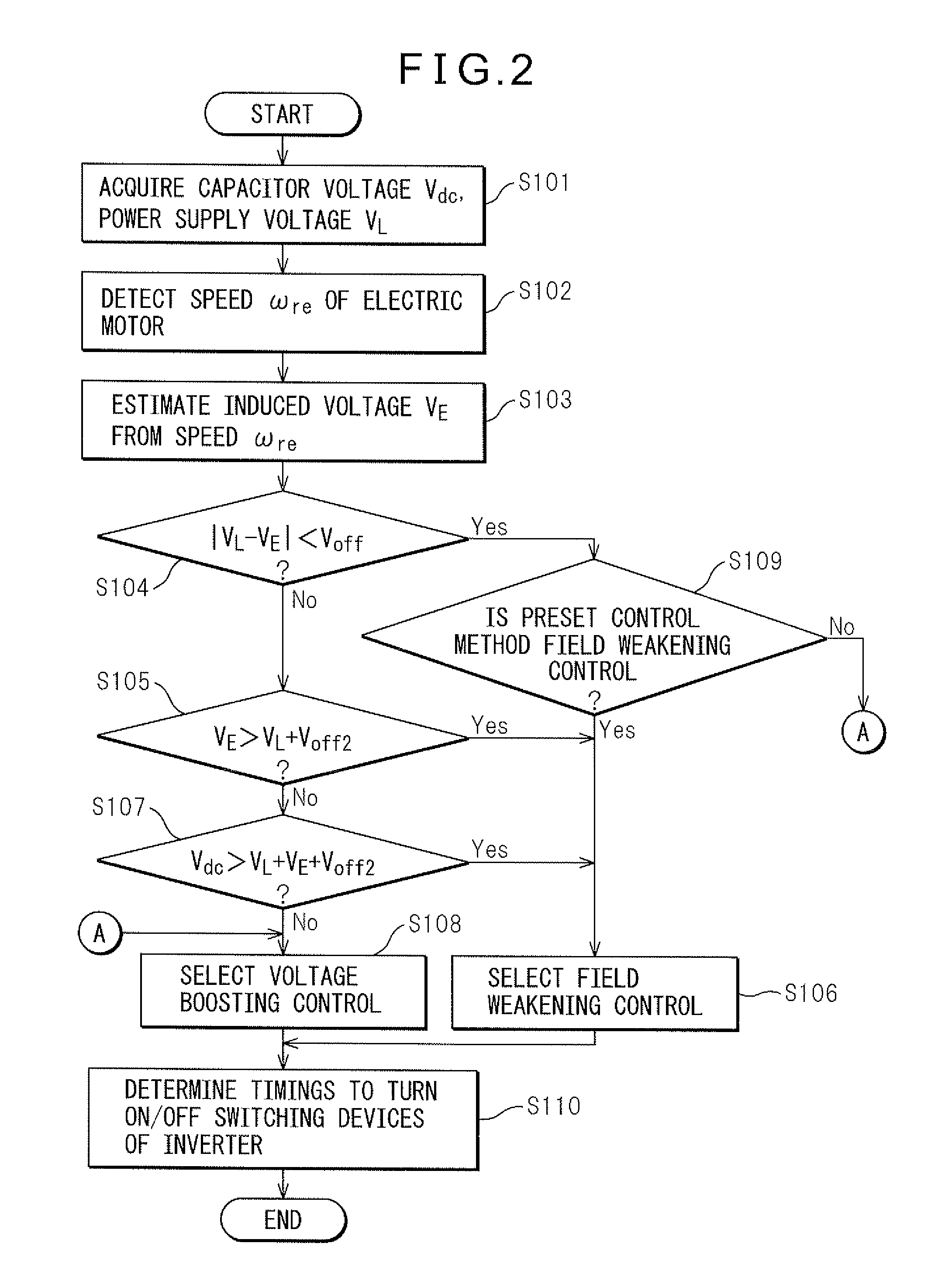
control circuit controlling the switching devices of the inverter so that the AC electric motor rotates at a designated speed. Further, the control circuit uses
field weakening control, which lowers the
induced voltage to control the switching devices of the inverter, when the induced voltage generated at the AC electric motor is larger than the
power supply voltage supplied by the DC power supply and, on the other hand, uses
voltage boosting control, which changes the amount of charging of the capacitor so as to change the voltage applied to the AC electric motor to control the switching devices of the inverter, when the induced voltage is smaller than the
power supply voltage. Due to this configuration, this electric motor drive device can reduce in the number of parts while improving the
energy conversion efficiency.
[0007]Further, preferably the control circuit uses predetermined control among the field weakening control and the
voltage boosting control so as to control the switching devices of the inverter when a difference of the
power supply voltage and the induced voltage is within a predetermined range. When the difference between the power supply voltage and the induced voltage is small, the higher
energy conversion efficiency control among the field weakening control and voltage boosting control is determined by the
assembly error of the AC electric motor and other factors. Therefore, by investigating which control among field weakening control and voltage boosting control will give a higher energy conversion efficiency when the difference between the power supply voltage and the induced voltage is within a predetermined range, this electric motor drive device can suitably select the control giving the higher energy conversion efficiency.
[0008]Further, preferably the electric motor drive device further includes an
ammeter which measures the current flowing through the AC electric motor, and, when the difference between the power supply voltage and the induced voltage is within a predetermined range, the control circuit uses field weakening control to control the switching devices of the inverter in the case where the value of the current is higher than a predetermined value and uses voltage boosting control the switching devices of the inverter in the case where the value of the current is that predetermined value or less. Due to this, this electric motor drive device can select the control method based on the results of measurement of the current actually flowing through the AC electric motor, so it is possible to select a higher efficiency control method in real time.
[0009]Furthermore, preferably the control circuit uses field weakening control to control the switching devices of the inverter when the induced voltage is smaller than the power supply voltage and the total of the power supply voltage and induced voltage is lower than the voltage across the terminals of the capacitor. Due to this, this electric motor drive device selects field weakening control when the amount of charging of the capacitor just increases even when raising the voltage supplied to the AC electric motor, so can improve the energy conversion efficiency more.
[0011]Furthermore, preferably the electric motor drive device further includes a status
signal acquiring unit which acquires a status
signal expressing a state of the
operating environment of the electric motor drive device, and wherein the control circuit uses values corresponding to the status
signal and designated speed among the values giving a predetermined indicator of induced voltage for a combination of the status signal and speed so as to estimate the induced voltage. Due to this, this electric motor drive device can accurately estimate the induced voltage even when the
operating environment of the AC electric motor changes.
[0012]Furthermore, as another aspect of the present invention, there is provided a control method of an electric motor drive device for driving an AC electric motor which includes a plurality of coils connected in a star configuration. The electric motor drive device to which this control method is applied includes an inverter including a plurality of arms, each of the plurality of arms corresponding to any one of the plurality of coils of the AC electric motor and including a first switching device connected to a positive rail and a second switching device connected in series between the first switching devices and a negative rail, wherein, for each of the plurality of arms, the midpoint of the first switching device and second switching device is connected with one end of the corresponding coil of the AC electric motor, and a capacitor charged by a current supplied from a DC power supply supplying
DC voltage between a neutral point to which the other ends of the coils of the AC electric motor are connected and a positive rail or negative rail of the inverter and passing through the inverter. Further, this control method includes comparing the induced voltage generated at the AC electric motor with the power supply voltage supplied by the DC power supply and using field weakening control, which lowers the induced voltage to control the switching devices of the inverter so that the AC electric motor rotates at a designated speed, when the induced voltage generated at the AC electric motor is larger than the power supply voltage supplied by the DC power supply and, on the other hand, using voltage boosting control, which changes the amount of charging of the capacitor so as to change the voltage applied to the AC electric motor to control the switching devices of the inverter, when the induced voltage is smaller than the power supply voltage. By including such a routine, this method of driving an electric motor can reduce the number of parts while improving the energy conversion efficiency.

