Self-oscillating switched mode converter with valley detection
- Summary
- Abstract
- Description
- Claims
- Application Information
AI Technical Summary
Benefits of technology
Problems solved by technology
Method used
Image

Examples
Embodiment Construction
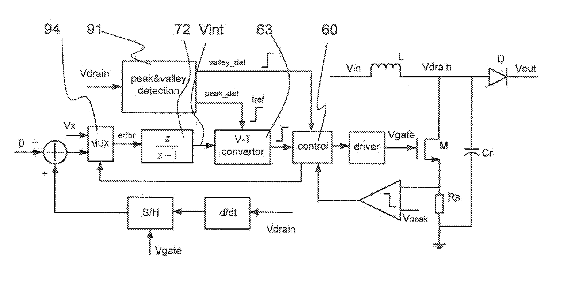
[0057]An embodiment of the invention comprising a boost converter is shown in FIG. 6. In overview, the switching error is measured at the moment when the switching device is turned on, and then the switching error is fed back to adjust the switch-on moment of the next cycle.
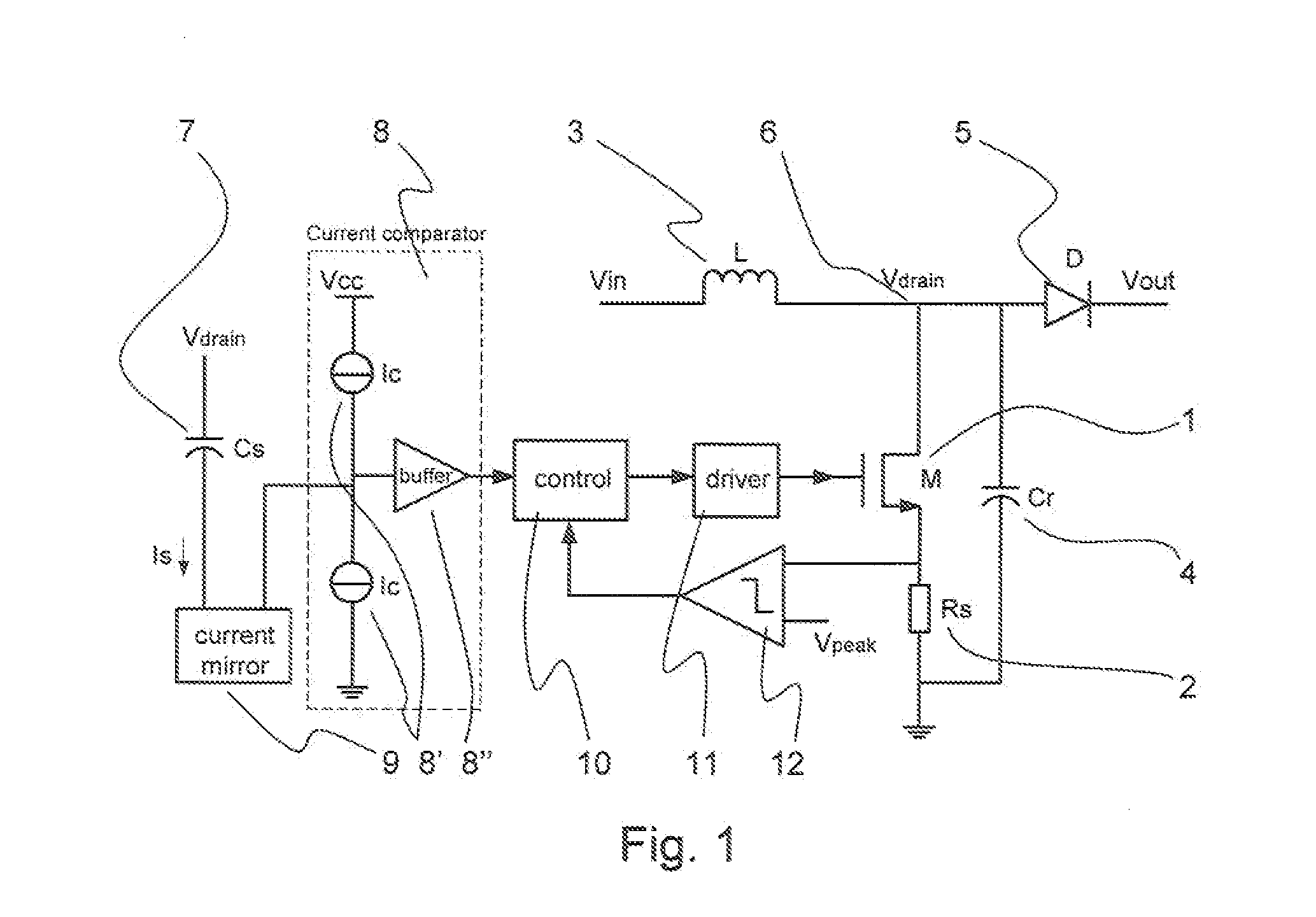
[0058]FIG. 6 shows a boost converter which, apart from the control, is similar to prior art converters. Thus it has a switch 1, the source of which is connected to sense resistor 2 that is used to sense inductor current, and define the maximum coil current. The drain of the switch forms switch node 6, which is connected to a voltage input (Vin) by inductor 3. The switch node 6 is connected to ground via capacitor 4, such that inductor 3 and capacitor 4 form a resonant tank. The switch node 6 is connected to the output voltage (Vout) by means of diode 4. The switch is driven by means of driver 11, under control of control logic 60.
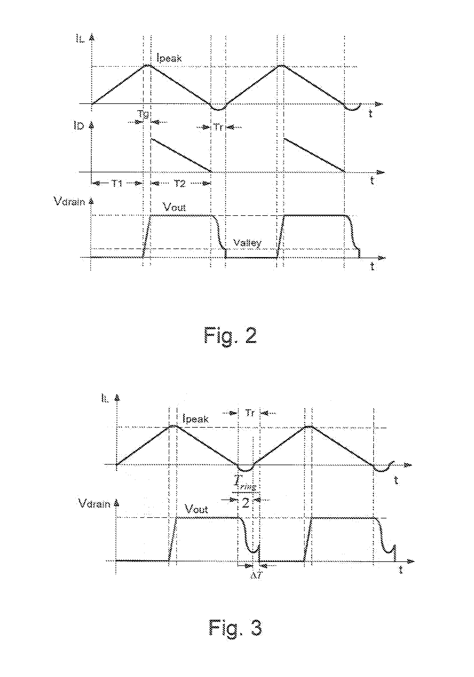
[0059]As shown on the plot of drain voltage (Vdrain), a fixed reference moment Tref ...
PUM
 Abstract
Description
Claims
Application Information
 - Generate Ideas
- Intellectual Property
- Life Sciences
- Materials
- Tech Scout
- Unparalleled Data Quality
- Higher Quality Content
- 60% Fewer Hallucinations
Browse by: Latest US Patents, China's latest patents, Technical Efficacy Thesaurus, Application Domain, Technology Topic, Popular Technical Reports.
© 2025 PatSnap. All rights reserved.Legal|Privacy policy|Modern Slavery Act Transparency Statement|Sitemap|About US| Contact US: help@patsnap.com