Apparatus for controlling integrated lighting ballasts in a series scheme

a technology of integrated lighting ballast and series scheme, which is applied in the direction of electric controllers, ignition automatic control, instruments, etc., can solve the problems of not being able to easily replace the light fixture and wall controls, not being able to tolerate many devices installed in close proximity, and not being able to achieve simple solutions for upgrading most legacy systems with plc-based lighting controls. , to achieve the effect of increasing data throughput, facilitating installation of the transmitter, and increasing reliability

Inactive Publication Date: 2011-02-10
GENERAL ELECTRIC CO
View PDF12 Cites 22 Cited by
  • Summary
  • Abstract
  • Description
  • Claims
  • Application Information

AI Technical Summary

Benefits of technology

[0002]A power line communication (PLC) system with a transmitter and receiver connected in series via a power distribution network, in which the transmitter has a switch controlled to selectively interrupt the current for relaying data to the receiver based on one or more user input signals or values, such as lamp dimming levels. The receiver is coupled in series with the transmitter via the power distribution network, and includes a rectifier and a driver circuit to selectively power a compact fluorescent lamp (CFL) or other lighting device, as well as a load control circuit operable by a receiver controller to selectively apply an auxiliary load to a load side of the rectifier. The load control circuit also operates as a data receiver which senses the transmitter-generated current interruptions and provides a data output to the controller. The receiver in some implementations includes a filter circuit with an inductance and a capacitance coupled between the receiver terminals and the rectifier. In certain embodiments, the transmitter sends multi-bit data to the transmitter via the power distribution network, and may include zero-crossing detection components to sense a zero crossing of AC current flowing in the power distribution network, and the data transmission is controlled to transmit the multi-bit data by selectively interrupting current flow at a time when the voltage of the AC power is almost zero. The use of several bits of information on each zero-crossing of the AC waveform advantageously increases data throughput, and the transmitter may use digital modulation with redundancy codes and / or error correcting codes to further increase reliability even in case of interference. The transmitter is self-powered in some embodiments, moreover, including a power supply circuit to receive power from the current sensor circuit and to supply power to the transmitter. In some embodiments, the transmitter switch circuit is a normally closed TRIAC circuit including a TRIAC. The series connection of the transmitter and receiver facilitates installation of the transmitter in place of a legacy switch to control the same appliances as were previously controlled by the switch, and the system mitigates or overcomes problems related to interference with similar devices in close proximity. The transmitter, moreover, can transmit periodically, thereby making the data communication fault-tolerant, and the use of a TRIAC or other semiconductor-based switching circuit in certain embodiments allows the transmitter to implement phase angle type dimming control if needed. The provision in the receiver of an auxiliary load circuit advantageously facilitates use of the PLC system with ballast driver circuits that do not provide power factor correction (PFC).

Problems solved by technology

However, the dimming controls and power distribution wiring for legacy incandescent bulbs typically do not allow direct replacement of the light fixture and wall controls.
Power Line Communications (PLC) systems provide intelligent communications between wall control units and lighting fixtures, but no simple solution exists for upgrading most legacy systems with PLC-based lighting controls.
The DALI bus, for example, requires installation of new wiring, and existing PLC schemes generally (e.g., such as X10) are often expensive, unreliable, do not tolerate many devices installed in close proximity, and cannot be directly connected in place of existing switches and dimmers.
Furthermore, the use of existing phase-angle controllers often leads to an unreliable installation (flickering) and requires sophisticated electronics in the ballast.

Method used


Image

  • Apparatus for controlling integrated lighting ballasts in a series scheme
  • Apparatus for controlling integrated lighting ballasts in a series scheme
  • Apparatus for controlling integrated lighting ballasts in a series scheme

Examples


Embodiment Construction

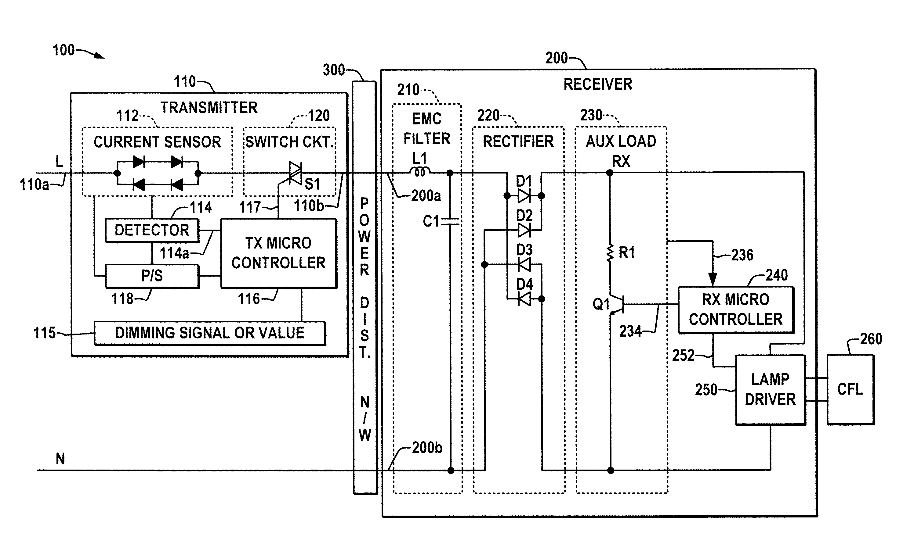
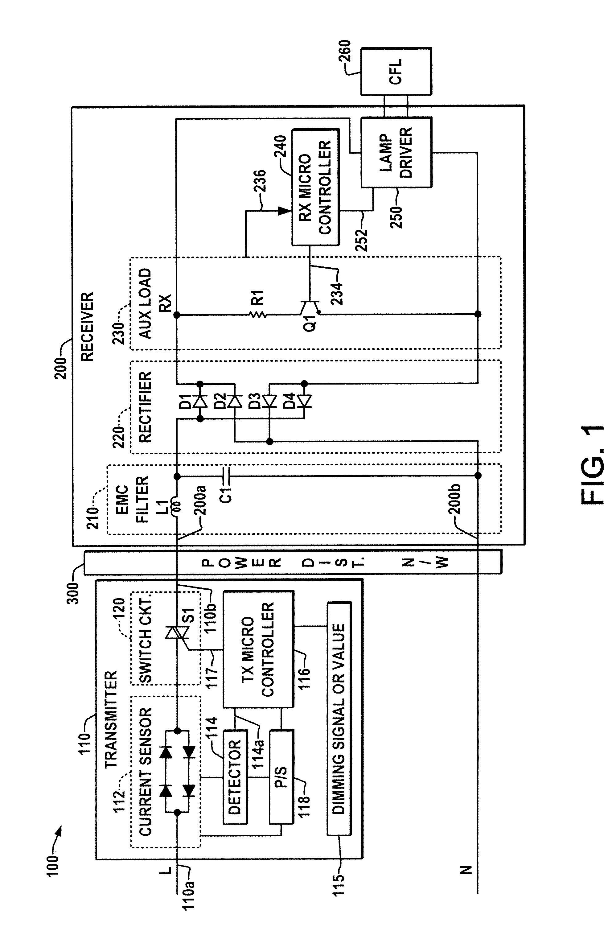
[0009]Referring now to the drawings, where like reference numerals are used to refer to like elements throughout, and wherein the various features are not necessarily drawn to scale, FIG. 1 illustrates a power line communication PLC system 100 that includes a transmitter 110 and a receiver 200 connected in series with one another by a power distribution network 300, such as legacy AC power wiring network in one example. The receiver 200 provides power to a compact fluorescent lamp (CFL) 260 via a lamp driver 250 in one example, but other forms of lighting devices may be driven by the receiver 200, including without limitation fluorescent tubes. The transmitter 110 includes an input 110a coupleable to a source of AC power, for example, such as a line (L) wire of a typical residential, commercial, industrial AC power wiring implementation, and an output 110b coupleable to a power distribution network 300, such as the wiring within walls etc. of the installation between a legacy switch...


PUM


Abstract

Power line communication (PLC) systems are presented for connecting dimming switches with electronic ballasts for driving compact fluorescent lamps and other applications using a power distribution network, including a transmitter and a receiver connected in a series circuit for transmission of multi-bit data, where the receiver has a load control circuit for selectively adjusting the receiver loading and to sense current interruptions to provide a data output.

Description

BACKGROUND OF THE DISCLOSURE[0001]Ballasts and other lamp drivers can be used in conjunction with dimming switches to selectively dim the light output of a lamp according to user settings. In many preexisting lighting systems, dimmer controlled incandescent bulbs are being replaced by fluorescent lamps in order to achieve energy savings and / or for regulatory compliance. Ballast systems provide electrical power to compact fluorescent lamps and other fluorescent lamps. Dimming ballasts are particularly popular, providing intelligent dimming features and other advanced lighting functionality not achievable with normal incandescent bulbs controlled by wall switches or dimmers. However, the dimming controls and power distribution wiring for legacy incandescent bulbs typically do not allow direct replacement of the light fixture and wall controls. Power Line Communications (PLC) systems provide intelligent communications between wall control units and lighting fixtures, but no simple solu...

Claims


Application Information

Patent Timeline
Patent Type & Authority Applications(United States)
IPC IPC(8): G05B11/01H05B41/38
CPCH05B41/295H05B37/0263H05B47/185
Inventor MAROS, ISTVANSZABO, SANDOR VIKTOR
Owner GENERAL ELECTRIC CO
Why Eureka
Try Eureka