LED lighting device module and LED lighting device

a technology of led lighting and led lighting, which is applied in the direction of semiconductor devices for light sources, fixed installations, lighting and heating apparatus, etc., can solve the problems of reducing the brightness of led, changing the wavelength, and generating heat, so as to reduce the cost, reduce the weight, and reduce the effect of total weigh

Inactive Publication Date: 2011-02-10
LEOTEK ELECTRONICS
View PDF13 Cites 26 Cited by
  • Summary
  • Abstract
  • Description
  • Claims
  • Application Information

AI Technical Summary

Benefits of technology

[0010]One particular aspect of the present invention is to provide an LED lighting device module and an LED lighting device. Its structure is simple, and the cost is reduced. The total weight is low, the heat can be easily exhausted, the LED lighting device can be easily manufactured and maintained, the LED lighting device can be expanded and the outline of the LED lighting device can be easily changed.
[0014]1. Because the light source structure and the power supply are located in the housing and the light source structure has a cooling device for exhausting heat, the housing is not used for exhausting heat. The material of the housing is not limited to a heat-conductive material and is not limited to be cast by metal. Both the cost and the weight are reduced.
[0016]3. The cover body is pivoted with the base body. When the lighting device is failed, the user merely needs to open the cover body to maintain the lighting device. The LED lighting device modules do not affect each other. The user merely needs to disassemble or replace the failed LED lighting device module. It is easy to maintain the lighting device.
[0018]5. The powers of the LED lighting device modules are independent so that the heat is distributed normally. The cooling effect is good. When one of the power supplies is failed, the lighting function of the lighting device will not fail due to just one the LED lighting device module is failed.

Problems solved by technology

When LED is lighting, a great amount of heat is generated so that a cooling device is required to exhaust the heat.
When the cooling device is not designed well, high temperature will lower the brightness of LED, reduce the usage life, and change the wavelength.
1. The LED lighting device 1a of the prior art usually has a housing 11a and an LED light source device 12a. The LED light source device 12a is directly pasted onto the housing 11a. The light source emits from the bottom of the housing 11a. The housing 11a has a cooling fin 111a with a large dimension to directly exhaust heat to air. However, dust will be accumulated on the housing 11a to affect the cooling effect. Moreover, the thickness of the housing 11a needs to be increased to make the heat be distributed uniformly and the housing 11a is made of heat-conductive metal. The cost and the weight increases.
2. The secondary optical design of the LED light source device 12a is a single mask. It is not easily expanded.
3. When the outline of the housing 11a needs to be changed, the structure of the LED lighting device 1a needs to be changed and the cooling device also needs to be changed.
4. A cooling pipe (not shown in the figure) is used to exhaust the heat of the LED. That will increase the cost and it is difficult to maintain the LED lighting device. Furthermore, due to the system dimension is increased and the LED lighting device becomes complex, it is not to assemble the LED lighting device.

Method used


Image

  • LED lighting device module and LED lighting device
  • LED lighting device module and LED lighting device
  • LED lighting device module and LED lighting device

Examples


Embodiment Construction

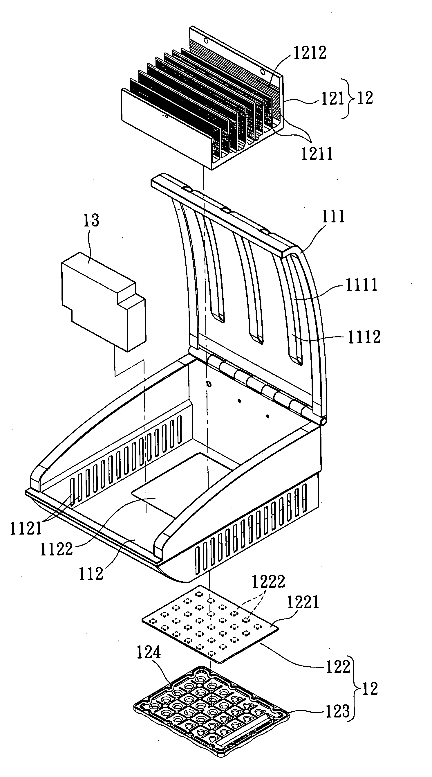
[0029]Reference is made to FIGS. 2˜6. The LED lighting device module 1 includes a housing 11, a light source structure 12 and a power supply 13.

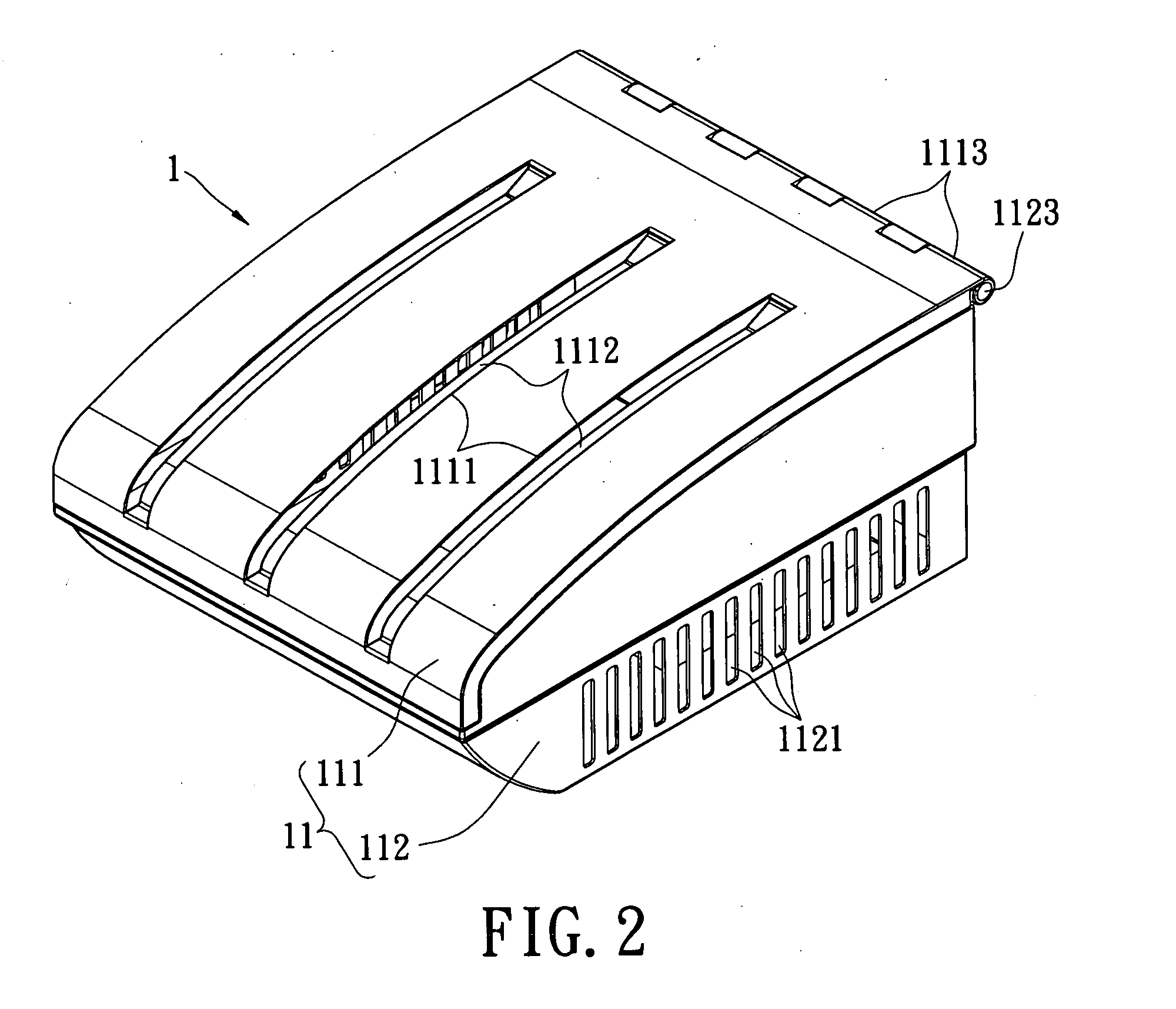
[0030]In this embodiment, the housing 11 is a hollow box. The material of the housing 11 is not limited to a heat-conductive material. For example, it can be a plastic part. The housing 11 includes a cover body 111 and a base body 112. The cover body 111 has a plurality of air outlets 1111, a plurality of concave portions 1112 and a plurality of pivoting portions 1113. The air outlets 1111 are bar-shaped and disposed on the top of the cover body 111 at intervals. The concave portions 1112 are respectively located at the air outlets 1111 and its height is lower than the cover body 111. The concave portion 1112 has a streamline shape and two ends of concave portion 1112 are respectively connected with the cover body 111 for preventing dust or rain from directly entering the housing 11. The pivoting portions 1113 extend and roll up to be formed...


PUM


Abstract

An LED light device module includes a housing, a light source structure and a power supply. The housing has a cover body and a base body. The cover body is located on the base body. The light source structure is located in the housing. The light source structure includes a cooling device, an LED light source device and a secondary optical device. The LED light source device and the secondary optical device are located on the cooling device. The LED light source device is located between the cooling device and the secondary optical device. The power supply is located in the housing and electrically connected with the light source structure. Thereby, the system cost is reduced, the total weight is low, it is easy to manufacture and maintain. The LED light device module can be expanded and the outline of the LED light device module can be designed flexibly.

Description

BACKGROUND OF THE INVENTION[0001]1. Field of the Invention[0002]The present invention relates to an LED lighting device module and an LED lighting device. In particular, the present invention relates to an LED lighting device module and an LED lighting device that can be expanded, easily maintained and its outline can be flexibly designed.[0003]2. Description of Related Art[0004]Because LED has a lot of merits, such as brightness is high, consumption power is low, and usage life is long, etc, LED is popularly applied to a variety of lighting devices, such as an LED lighting device for lighting a road. When LED is lighting, a great amount of heat is generated so that a cooling device is required to exhaust the heat. Therefore, LED can light under a proper temperature and does not burn down. When the cooling device is not designed well, high temperature will lower the brightness of LED, reduce the usage life, and change the wavelength. Furthermore, because the height and the required ...

Claims


Application Information

Patent Timeline
Patent Type & Authority Applications(United States)
IPC IPC(8): F21L4/00
CPCF21S8/086F21V29/004F21W2131/103F21V29/83F21V29/2212F21V29/75F21V29/76F21Y2101/02F21Y2115/10
Inventor HU, SHENG-HSIUNGYEH, YU-YUANLEE, CHING-PO
Owner LEOTEK ELECTRONICS
Why Eureka
Try Eureka