Imaging Device and Video Recording/Reproducing System

a technology of video recording and recording system, applied in the field of imaging device, can solve problems such as difficulty in miniaturizing devices, and achieve the effect of simplifying the structure of optical systems

Active Publication Date: 2011-02-10
SONY CORP
View PDF5 Cites 29 Cited by
  • Summary
  • Abstract
  • Description
  • Claims
  • Application Information

AI Technical Summary

Benefits of technology

[0012]According to the embodiments of the present invention, it is possible to simplify the structure of an optical system upon stereoscopic photographing and to miniaturize an imaging device.

Problems solved by technology

Accordingly, since light loss occurs in the lens system, it is difficult to miniaturize the device.

Method used


Image

  • Imaging Device and Video Recording/Reproducing System
  • Imaging Device and Video Recording/Reproducing System
  • Imaging Device and Video Recording/Reproducing System

Examples


first embodiment

1. FIRST EMBODIMENT

Configuration Example of Imaging Device

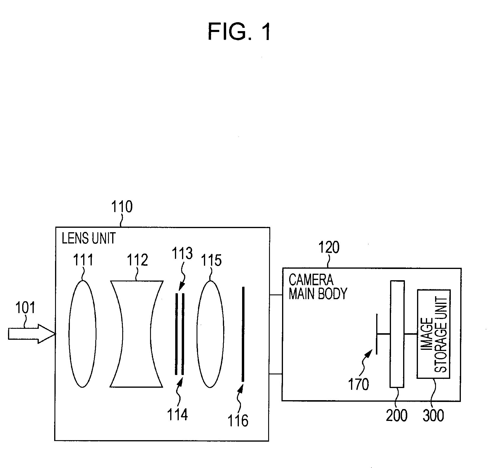
[0025]FIG. 1 is a top cross-sectional view of an example of an imaging device according to an embodiment of the present invention. This imaging device receives incident light 101 from a subject, splits the light to the left and right by a polarization filter 114, forms an image on an imaging element 170, and generates left and right video data. This imaging device includes a lens unit 110 on the pre-stage of a camera main body 120.

[0026]The lens unit 110 includes photographing lenses 111 and 112, a diaphragm 113, a polarization filter 114, and an imaging lens 115.

[0027]The photographing lenses 111 and 112 are lens for focusing the incident light 101 from the subject. These photographing lenses 111 include a focus lens for focusing, a zoom lens for enlarging the subject, and the like, and are generally realized by a combination of a plurality of lenses in order to correct chromatic aberration.

[0028]The diaphragm 113 has a narr...

second embodiment

2. SECOND EMBODIMENT

Configuration Example of Video Recording / Reproducing System

[0054]FIG. 7 is a diagram showing a configuration example of a video recording / reproducing system according to an embodiment of the present invention. This video recording / reproducing system includes an imaging unit 100, a video recording unit 200, a video storage unit 300, a video reproduction unit 400, and a display unit 500.

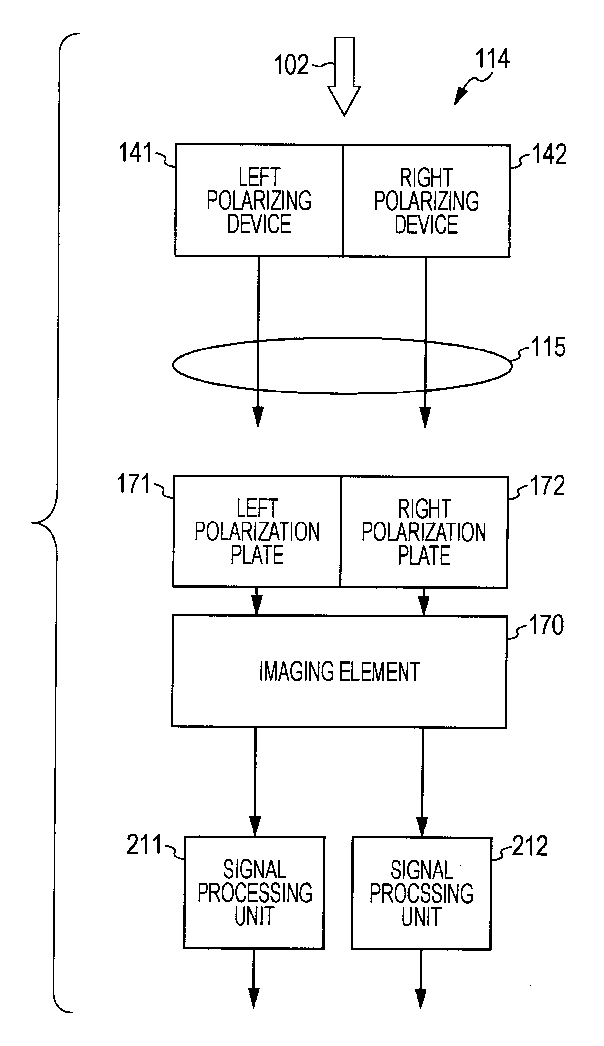
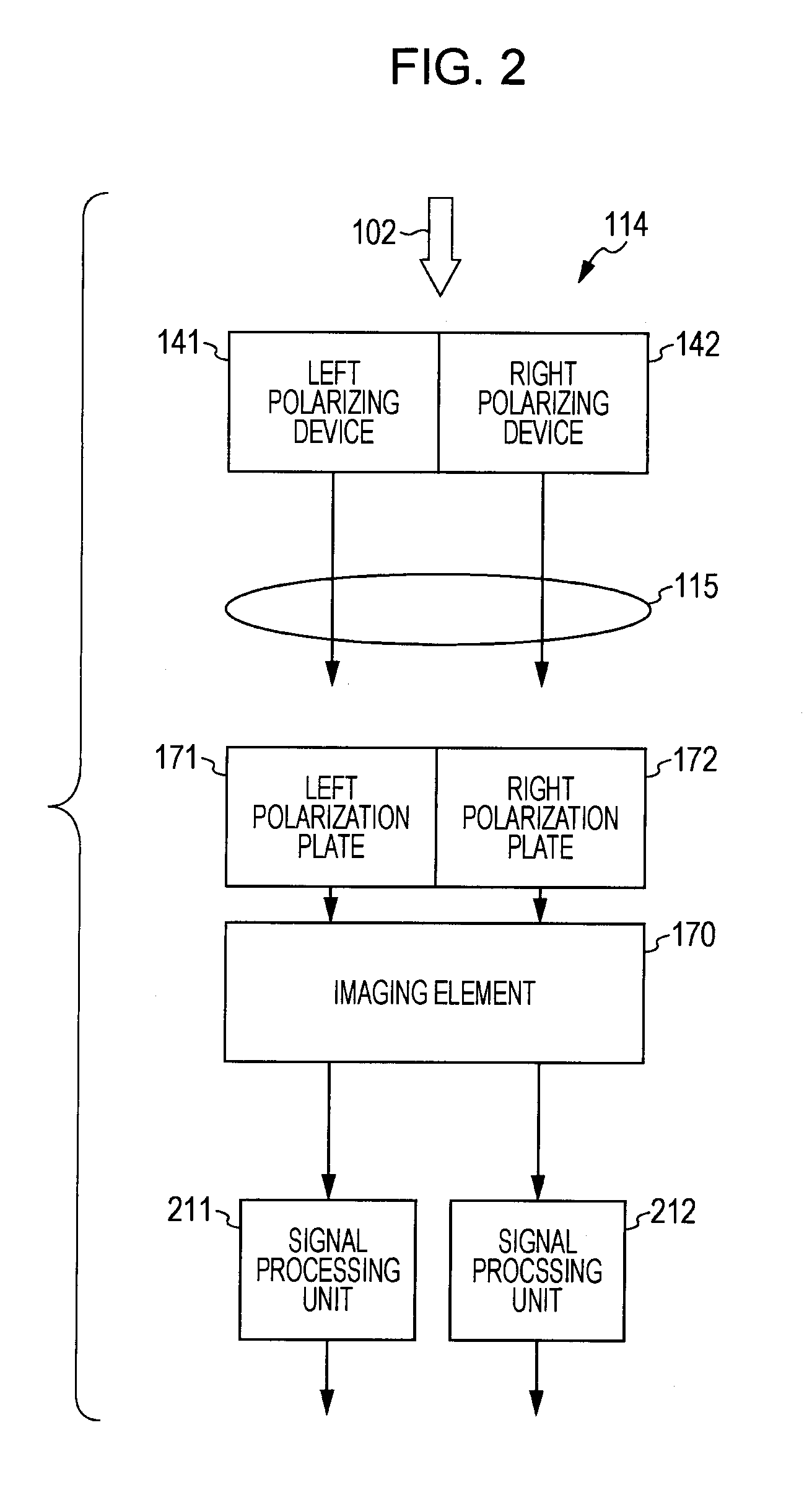
[0055]The imaging unit 100 corresponds to the above-described imaging device, receives incident light from a subject, and generates left and right images 610 and 620 in a tooth missing state by the imaging element 170.

[0056]The video recording unit 200 performs demosaic processing and interpolation processing with respect to the left and right images 610 and 620 output from the imaging unit 100 and records a left-eye image 630 and a right-eye image 640 in the video storage unit 300. This video recording unit 200 includes signal processing units 211 and 212, image memories 221 and 22...


PUM


Abstract

Disclosed herein is an imaging device that includes a photographing lens configured to focus light from a subject, a splitter configured to split the focused light to left and right in an area, in which light diffused from one point of the subject becomes parallel light, so as to respectively form different polarized lights, an imaging lens configured to respectively image the split different polarized lights, a transmission unit configured to receive the imaged different polarized lights on the same plane so as to transmit any one of the polarized lights in each area of the plane, an imaging element configured to convert the transmitted light on the plane into an image according to an electronic signal, and an image generating unit configured to extract and interpolate the converted image in each area so as to generate two different images.

Description

BACKGROUND OF THE INVENTION[0001]1. Field of the Invention[0002]The present invention relates to an imaging device and, more particularly, to an imaging device for picking up a subject as a stereoscopic image and a video recording / reproducing system.[0003]2. Description of the Related Art[0004]In the related art, a system for simultaneously picking up a common subject using two left and right video cameras and simultaneously outputting the left and right videos so as to display a stereoscopic image was proposed. However, if the two video cameras are used, the size of the device is enlarged and thus this system is not practical. In addition, a base length (baseline) between the two video cameras, that is, a distance between both eyes of a stereoscopic camera, is generally about 65 mm corresponding to a distance between both eyes of a human, regardless of a zoom ratio of a lens. In this case, in a video subjected to zooming, visual disparity is increased and the visual system is force...

Claims


Application Information

Patent Timeline
Patent Type & Authority Applications(United States)
IPC IPC(8): G03B7/00G03B35/08H04N5/225H04N13/02
CPCG03B7/00H04N13/337
Inventor KUROKI, YOSHIHIKO
Owner SONY CORP
Why Eureka
Try Eureka