Sensor system for motion control of a moving unit and a method of installing a sensor system for motion control of a moving unit

a technology of moving unit and sensor system, which is applied in the direction of braking system, instruments, manufacturing tools, etc., can solve the problems of deteriorating accuracy of acceleration detection on the desired detection axis, preventing accurate motion control, and reducing the degree of mingling foreign acceleration components. , to achieve the effect of suppressing the degree of mingling foreign acceleration components, suppressing the positional fluctuation of the detection axis, and preventing the delay of detection information

Inactive Publication Date: 2011-02-10
HITACHI CABLE
View PDF3 Cites 19 Cited by
  • Summary
  • Abstract
  • Description
  • Claims
  • Application Information

AI Technical Summary

Benefits of technology

[0029]The present invention provides a sensor system for motion control of a moving unit and a method of installing a sensor system for motion control of a moving unit, wherein the system is capable of preventing delay of the detection information generated in response to the reaction force received from the road surface by installing the sensors, such as acceleration sensors, in the unsprung mass of a moving unit such as a vehicle and is capable of maintaining the detection accuracy of the sensors on the detection axis high suppressing the positional fluctuation of the detection axis of the sensor caused by the movements of a vehicle deviating from the coordinate axis defined based on the standing-still state of a vehicle.
[0049]Since the present invention employs such a configuration that a sensor, such as an acceleration sensor, is arranged on a vibration-buffering member that is a structural element of the suspension device of a moving unit such as a vehicle, a sensor system for motion control of a moving unit and a method of installing a sensor system for motion control of a moving unit are provided, wherein the system is capable of preventing the delay of the detection information generated in response to the reaction force received from the road surface and is capable of maintaining the detection accuracy of the sensors on the detection axis high suppressing the positional fluctuation of the detection axis of the sensor caused by the movements of the vehicle deviating from the coordinate axis defined based on the standing-still state of the vehicle.
[0050]The sensor system for motion control of a moving unit of the present invention or the method of installing a sensor system for motion control of a moving unit of the present invention, or both, suppress the positional deviation of the detection axis of the sensor, such as the acceleration sensor, from the coordinate axis defined based on the standing-still state of the vehicle, to which variations in the camber angle and the caster angle caused from movements of a vehicle and variations in the lean of the vehicle itself in lateral or longitudinal direction are responsible. Thereby, it becomes practicable to suppress the degree of mingling foreign acceleration component on an axis other than the detection axis of the sensor with the detection accuracy on the detection axis of the sensor enhanced.
[0051]Further to the above, the system of the present invention prevents the delay of the detection information generated in response to the reaction force received from the road surface, since the installation method stated above arranges the sensor such as an acceleration sensor in the unsprung mass of the moving unit such as a vehicle. Therefore, a synergy with the highly accurate sensor output on the detection axis of sensor as stated above makes it possible to control movement of an automobile with high accuracy.

Problems solved by technology

Therefore, information delay occurs while the reactive force from the road surface is transmitted through the unsprung mass parts; this has caused a problem in that an accurate motion control is prevented.
If the detection axis of an acceleration sensor, which is installed according to the coordinate axis defined based on the standing-still state of a vehicle, moves right or left because of variation of the camber angle caused from the movement of the vehicle such as turning resulting in its positional deviation from the above-stated coordinate axis, the acceleration value detected by the acceleration sensor may have a risk of having a foreign acceleration component on a detection axis other than the desired detection axis mingled therewith.
The inclusion of foreign acceleration component on an axis other than the desired detection axis invites a reduction of amount in the detected value of the acceleration component on the desired detection axis developing into such a problem that the accuracy of the acceleration detection on the desired detection axis deteriorates.
As stated above, when sensors for such control system, particularly acceleration sensors, are installed on the parts in the unsprung mass such as the knuckle and the hub intending to prevent delay of the detection information generated from the sensor of the motion control system of a moving unit such as a vehicle in response to the reaction force received from the road surface, a positional fluctuation occurs on the detection axis of the sensor deviating from the coordinate axis defined based on the standing-still state of the vehicle leading to such a problem that the accuracy of the detection on the desired detection axis of the sensor deteriorates.

Method used


Image

  • Sensor system for motion control of a moving unit and a method of installing a sensor system for motion control of a moving unit
  • Sensor system for motion control of a moving unit and a method of installing a sensor system for motion control of a moving unit
  • Sensor system for motion control of a moving unit and a method of installing a sensor system for motion control of a moving unit

Examples


first embodiment

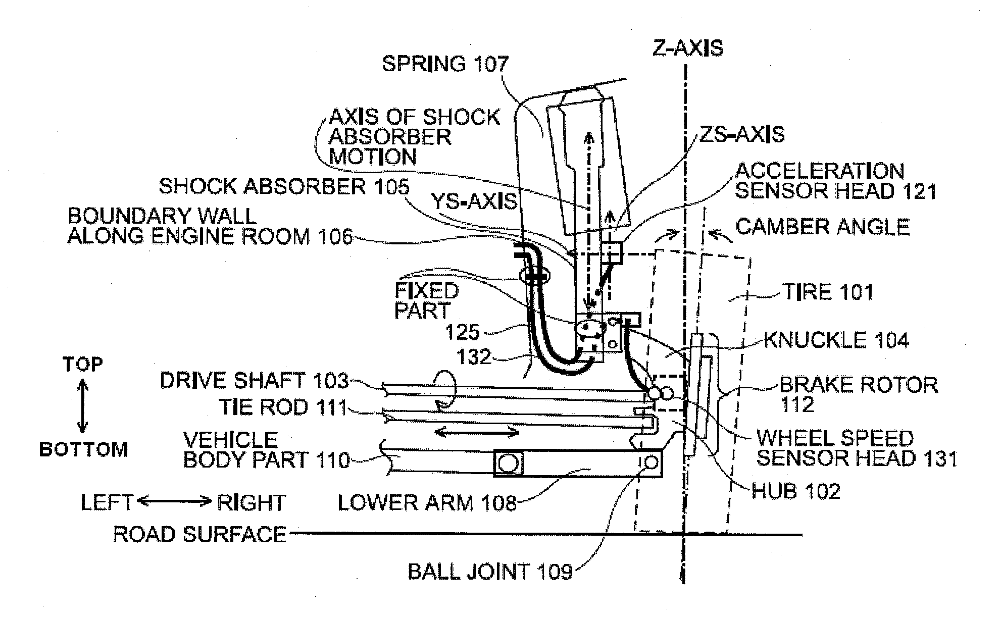
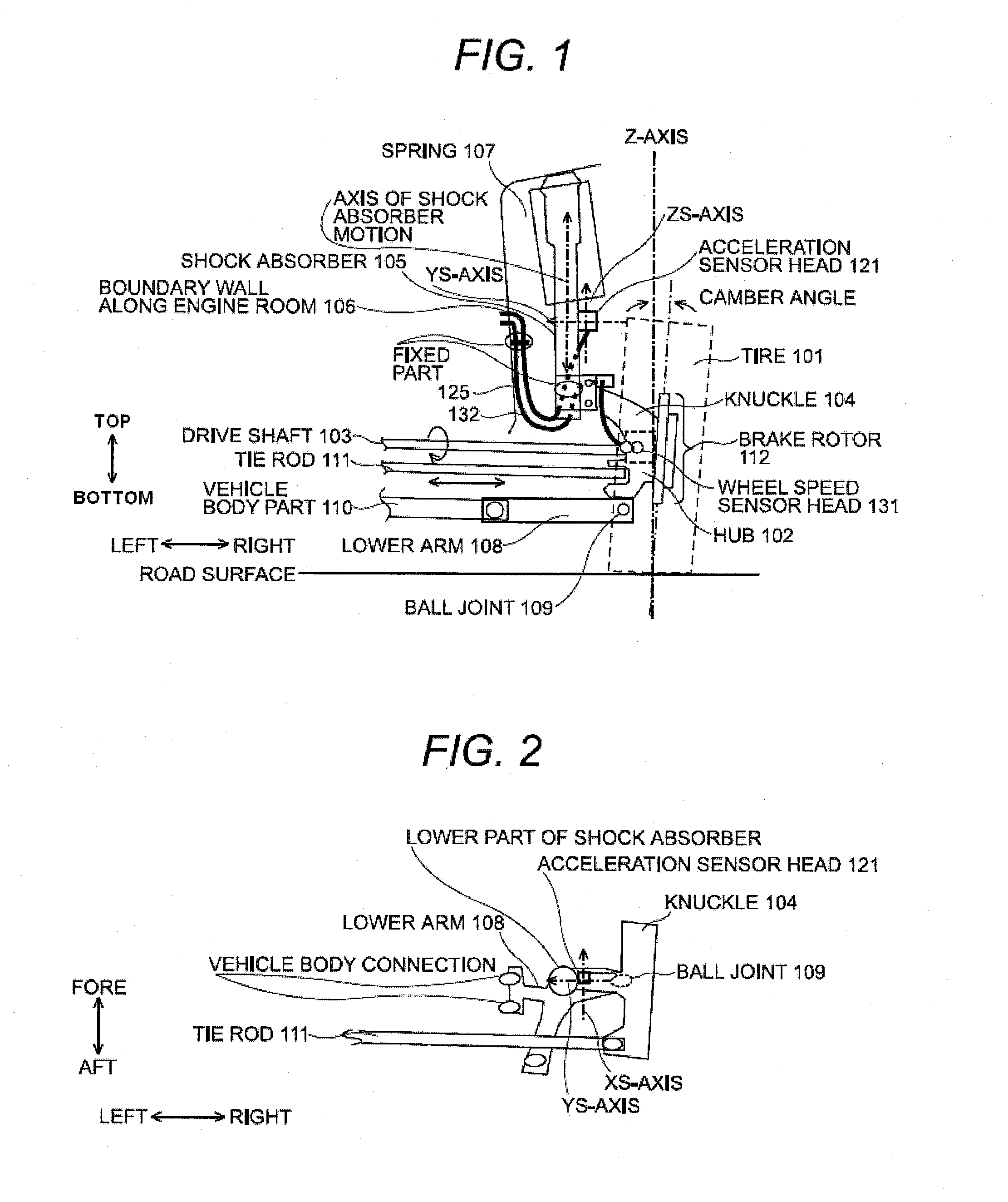
[0073]the present invention will be explained with reference to FIGS. 1, 2, and 3. The sensor system for motion control of a moving unit shown in FIG. 1 is a system configuration where an acceleration sensor is installed on the right wheel of the front wheel drive car indicated in FIG. 18 given as an example of conventional arrangement.

[0074]Arrows indicating directions of fore-and-aft, right-left, and top-bottom are defined taking the car body as the reference point. Hereinafter, the same definition of the directions fore-and-aft, right-left, and top-bottom is applied also to the explanation of other embodiment of the present invention.

[0075]In this embodiment, an acceleration sensor head 121 having a built-in acceleration sensor, which is a physical value sensor, is installed in the unsprung mass of a shock absorber 105, which is a vibration-buffering member. The shock absorber 105 and a spring 107 include the suspension device of the car.

[0076]In this embodiment, the acceleration...

embodiment 1

[0083]The explanation of the present invention provided up to this point took the right-side front wheel of the car as an explanatory configuration. When the acceleration sensor head 121 is to be installed on the other wheel of the car, the same manner as explained above is applicable. That is, although the axis of the shock absorber 105 motion differs in each wheel, it satisfies the required conditions to install the acceleration sensors so that the zs-axes of the sensors will be severally in parallel with the axis of the shock absorber 105 motion on the corresponding wheel.

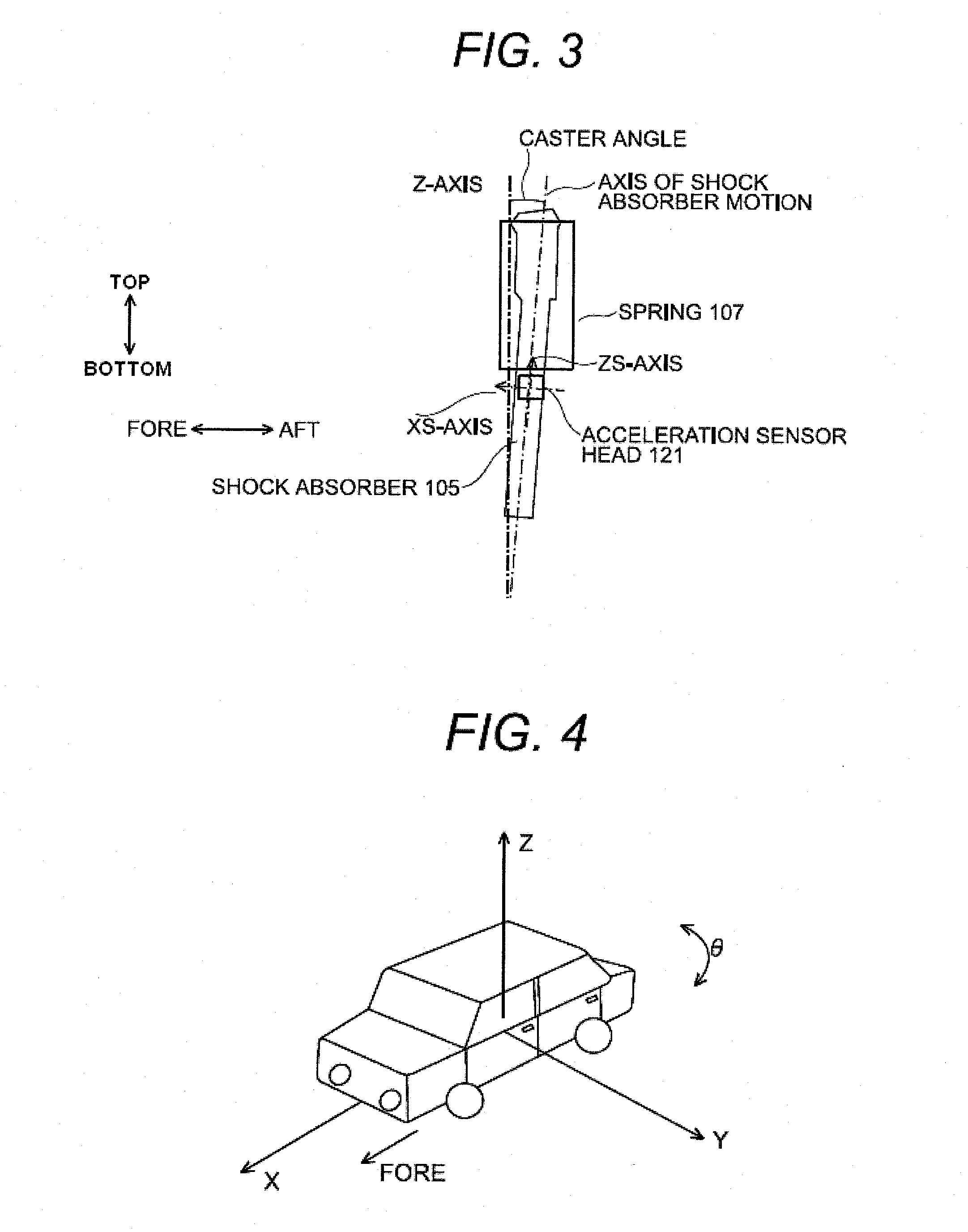
[0084]The following explains the principle of the present invention with reference to the embodiment 1 of the present invention.

[0085]FIG. 4 shows the definition of the coordinate used in the description of the present invention. In the present invention as FIG. 4 shows, the fore-and-aft direction is defined as the x-axis, the right-left direction the y-axis, and the top-bottom direction the z-axis, taking a car...

second embodiment

[0119]the present invention will be explained with reference to FIG. 8. This embodiment selects the distal end of a shock absorber 105, which is a vibration-buffering member, as the place of installing an acceleration sensor head 121.

[0120]In this embodiment, the acceleration sensor head 121 having a built-in acceleration sensor, which is a physical value sensor, is rigidly held at the distal end of the shock absorber 105, which is a vibration-buffering member.

[0121]The acceleration sensor head 121 used in this embodiment has, similarly to the first embodiment, three built-in uniaxial acceleration sensors each with one detection axis. These three acceleration sensors are built within the acceleration sensor head 121 with their detection axes direction changed so that each of which will severally detect acceleration in the directions of the x-axis, the y-axis, and the z-axis.

[0122]In this embodiment, the acceleration sensor head 121 is rigidly held at the distal end of the shock abso...


PUM

PropertyMeasurementUnit
temperaturesaaaaaaaaaa
accelerationaaaaaaaaaa

Abstract

A sensor system for motion control of a moving unit such as a vehicle, which is comprised of a uniaxial physical value sensor having a single detection axis and the uniaxial physical value sensor being installed in a unsprung mass of a suspension device provided in the moving unit, wherein the detection axis of the uniaxial physical value sensor and the working axis of a vibration-buffering member provided on the suspension device are approximately parallel.

Description

[0001]The present application is based on Japanese Patent Application No. 2009-182281 filed on Aug. 5, 2009, the entire contents of which are incorporated herein by reference.TECHNICAL FIELD[0002]The present invention relates to a sensor system for motion control of a moving unit such as an automobile or a rail car that has a suspension device and relates to a method of installing a sensor system for motion control of such moving unit.BACKGROUND ART[0003]For improvement of driving-braking performance and quality of handling stability of a moving unit such as an automobile or a rail car that has a suspension device (hereinafter referred to as a vehicle or vehicles), such a system as controls the driving-braking of a vehicle and the steering of each of the wheels of the vehicle responding to measurements obtained by measuring the motion of the vehicle has been developed.[0004]For example, the anti-lock braking system (ABS) and the traction control system (TCS), which work on the suppr...

Claims


Application Information

Patent Timeline
Patent Type & Authority Applications(United States)
IPC IPC(8): G06F7/00B23P11/00
CPCB60G2204/112B60G2204/202B60G2400/102B60G2400/104Y10T29/49826B60G2400/208B60G2401/90B60T8/171B60G2400/106
Inventor YAMAMOTO, SATOSHI
Owner HITACHI CABLE
Why Eureka
Try Eureka