Door panel

Active Publication Date: 2011-02-17
SHIN CATERPILLAR MITSUBISHI LTD CORP
View PDF8 Cites 2 Cited by
  • Summary
  • Abstract
  • Description
  • Claims
  • Application Information

AI Technical Summary

Benefits of technology

[0012]Accordingly, the vertically extending rib portions are formed within the flat adhering portions, which are surrounded by the frame-like reinforcing raised portion and the crossbar-shaped reinforcing raised portions of the inner panel and joined to the outer panel. Each adhering portion includes an opening cutout portion, which can be cut out for formation of a ventilation opening and includes portions that extend uninterruptedly at locations respectively adjacent to the upper and lower ends of the rib portions of the adhering portion. The rib portions prevent deformation and improve the rigidity of the adhering portions. Furthermore, it is possible to form a large ventilation opening in each adhering portion without significantly impairing the shape or the strength of the door panel by cutting out the ventilation opening from the adhering portion, together with the rib portions, along the periphery of the opening cutout portion, which extends uninterruptedly without intersecting the rib portions. The door panel according to the invention can thus be easily modified to withstand severe heat. Furthermore, a clean-cut surface is ensured, because the door panel according to the invention is free from the

Problems solved by technology

In cases where the door panel were to be modified to withstand severe heat

Method used


Image

  • Door panel
  • Door panel
  • Door panel

Examples


Example

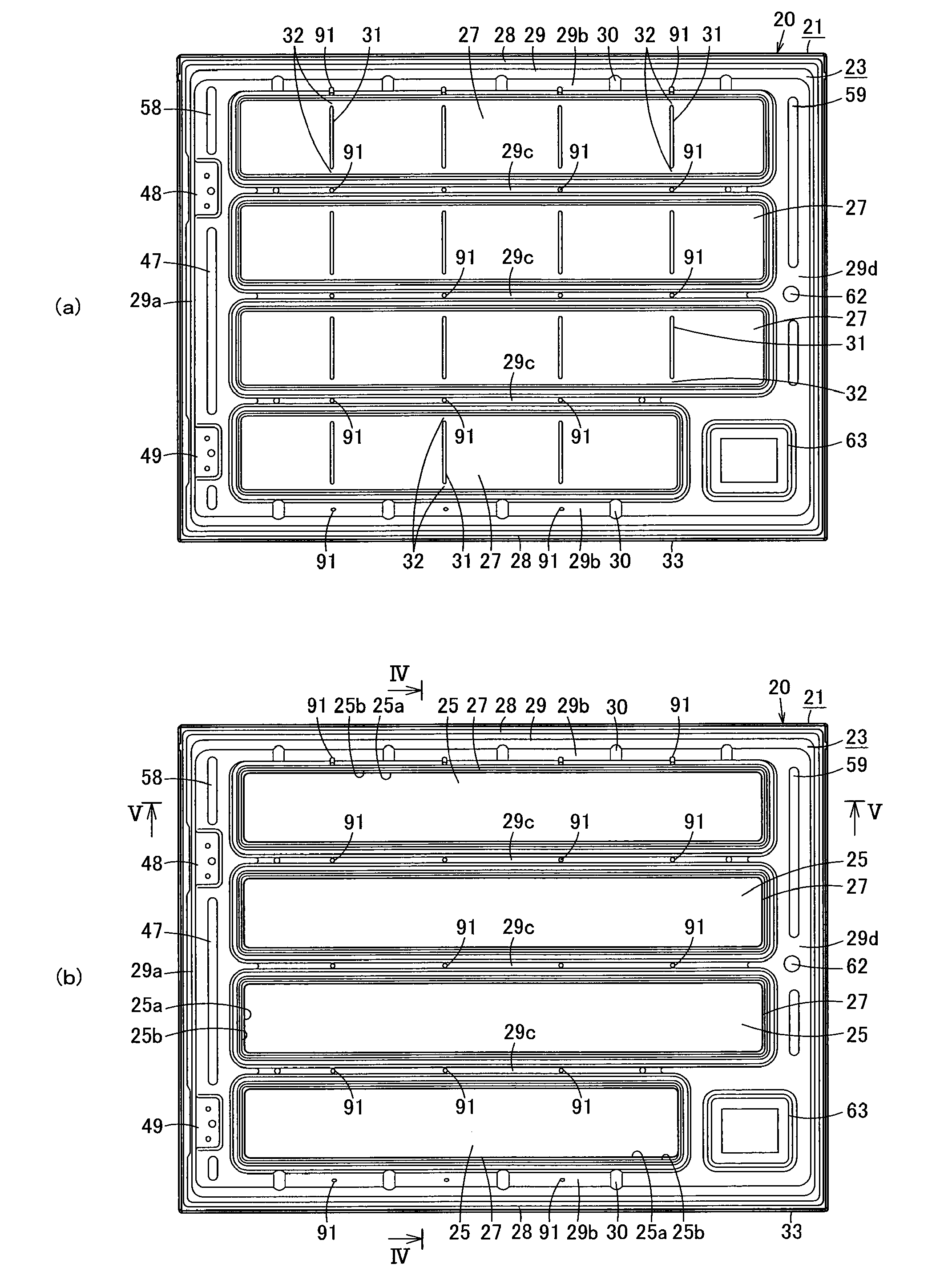
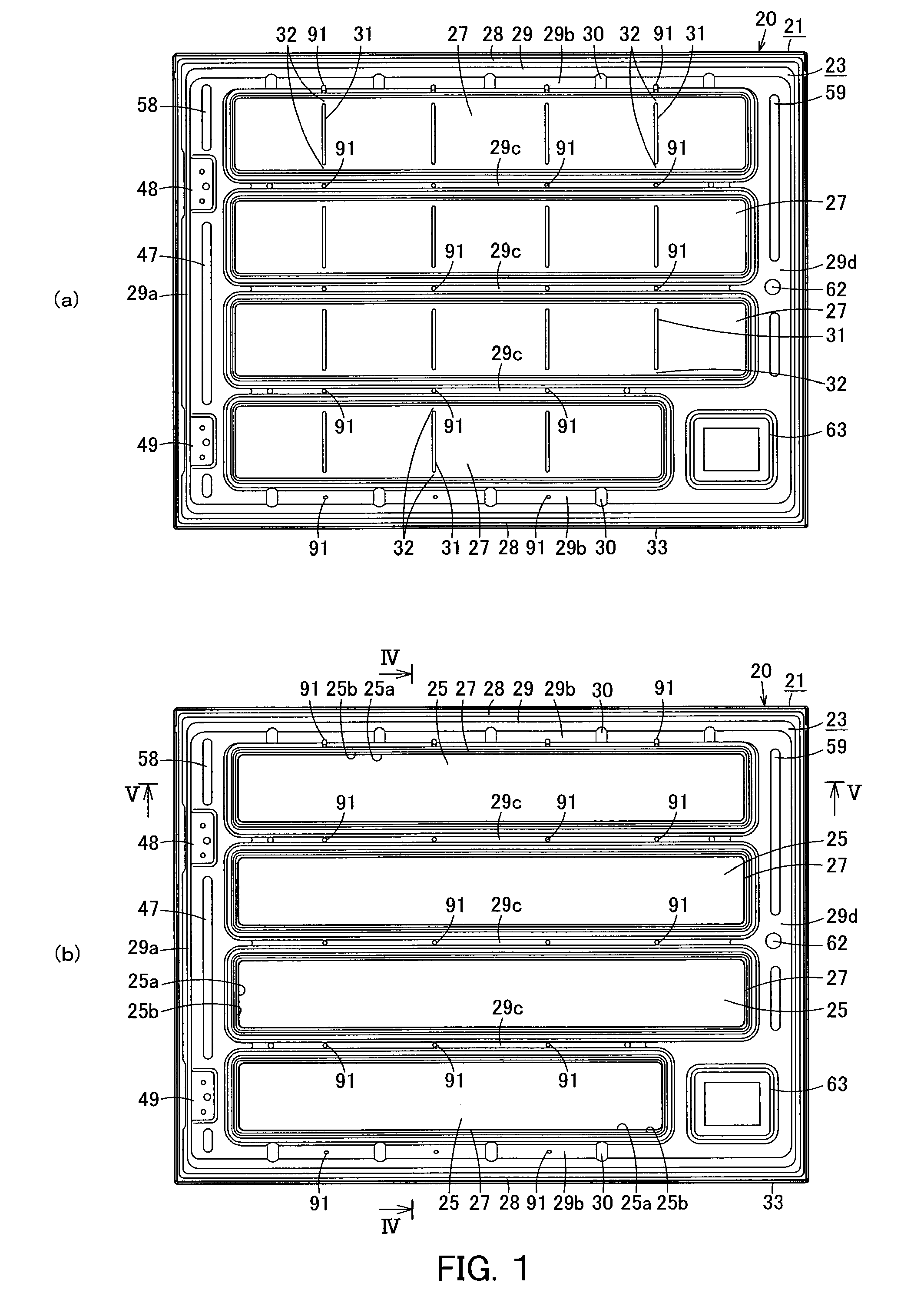
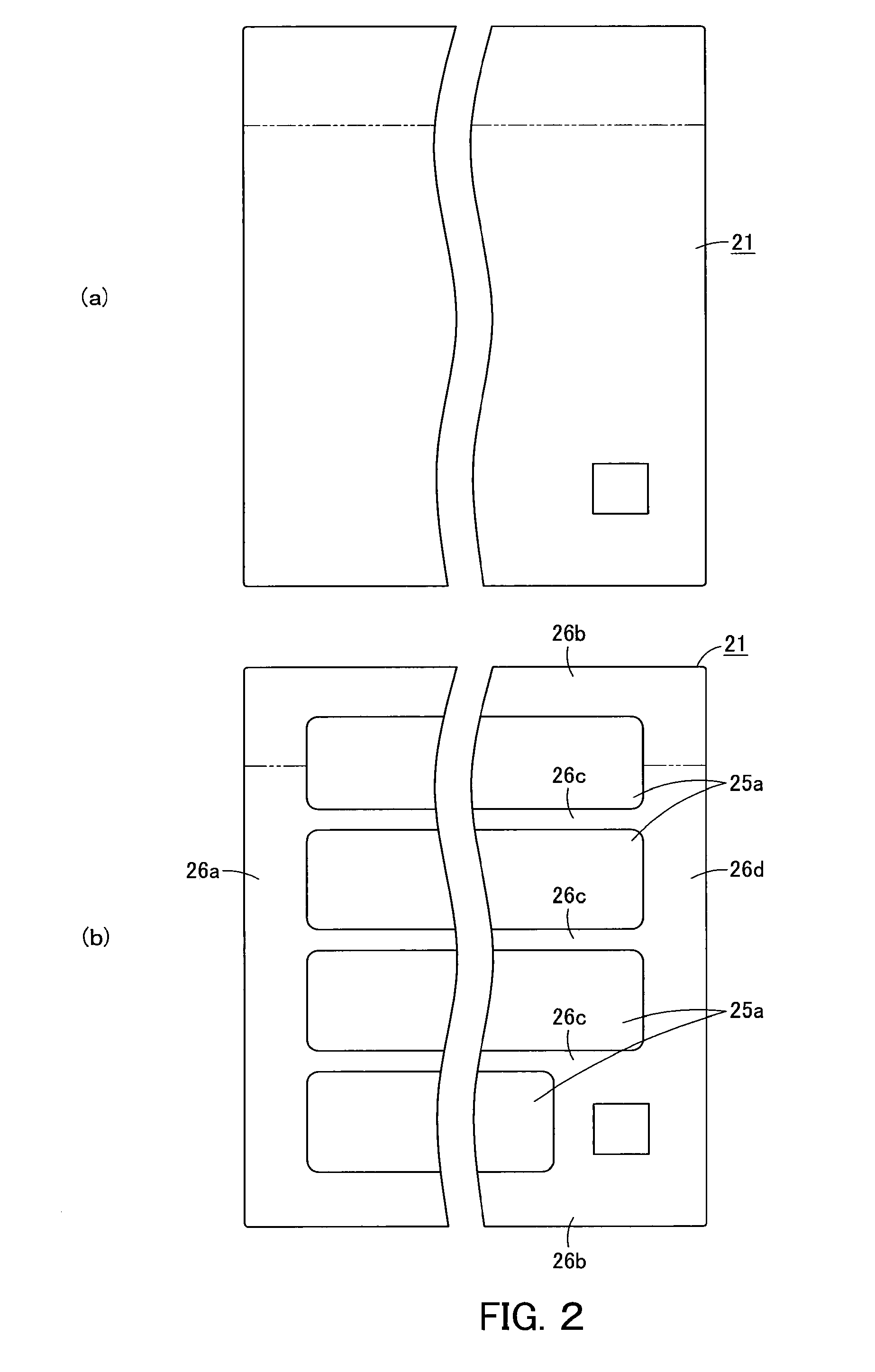
[0031]Next, the present invention is explained in detail hereunder, referring to an example thereof illustrated in FIGS. 1 to 8, another example thereof illustrated in FIG. 9, a further example thereof illustrated in FIG. 10, yet another example thereof illustrated in FIG. 11, an example thereof illustrated in FIG. 12, and a further example thereof illustrated in FIG. 13.

[0032]An example is illustrated in FIGS. 1 to 8.

[0033]FIG. 7 illustrates a hydraulic excavator 10, which is a work machine. The hydraulic excavator 10 includes a lower structure 11, an upper structure 12, a cab 13, a work equipment 14, and a power system 15 that includes an engine. The cab 13, the work equipment 14, and the power system 15 are mounted on the upper structure 12, which is rotatably mounted on the lower structure 11. The power system 15 is covered by a top cover 16, side doors 17, and other such components.

[0034]FIG. 8 illustrates a side door 17 provided at the radiator room. The side door 17 is attach...


PUM


Abstract

The present invention provides a door panel that comprises an outer panel and an inner panel joined together at adhering portions and, regardless of whether rib portions are formed on the adhering portions in order to prevent deformation of the adhering portions or for other purpose, can be modified to withstand severe heat by means of formation of large ventilation openings in the adhering portions without significantly impairing the shape or the strength of the door panel.

Description

CROSS REFERENCE TO PRIOR APPLICATIONS[0001]This application is a U.S. National Phase application under 35 U.S.C. §371 of International Application No. PCT / JP2009 / 059686, filed on May 27, 2009 and claims benefit of priority to Japanese Patent Application No. 2008-208621, filed on Aug. 13, 2008. The International Application was published in Japanese on Feb. 18, 2010 as WO 2010 / 018705 A1 under PCT Article 21(2). All of these applications are herein incorporated by reference.TECHNICAL FIELD[0002]The present invention relates to a door panel with a double-panel structure comprising an outer panel and an inner panel.BACKGROUND OF THE INVENTION[0003]FIG. 14 illustrates a hydraulic excavator 10 including a lower structure 11, an upper structure 12, a cab 13, a work equipment 14, and a power system 15 that includes an engine. The cab 13, the work equipment 14, and the power system 15 are mounted on the upper structure 12, which is rotatably mounted on the lower structure 11. The power syste...

Claims


Application Information

Patent Timeline
IPC IPC(8): E06B5/00E06B3/72
CPCB60K11/08E02F9/0891E02F9/00B62D25/10
Inventor UTO, RYOJITAKEUCHI, SHIGEMI
Owner SHIN CATERPILLAR MITSUBISHI LTD CORP
Why Eureka
Try Eureka