Light emitting module, heat sink and illumination system

a technology of light emitting modules and heat sinks, applied in the direction of discharge tube main electrodes, semiconductor devices of light sources, lighting and heating apparatus, etc., can solve the problems of insufficient cooling of light sources, damage to light sources, and increase the chance of cooling fluid leakage, so as to reduce complexity

a technology of light emitting modules and heat sinks, applied in the direction of discharge tube main electrodes, semiconductor devices of light sources, lighting and heating apparatus, etc., can solve the problems of insufficient cooling of light sources, damage to light sources, and increase the chance of cooling fluid leakage, so as to reduce complexity

US20110037369A1Active Publication Date: 2011-02-17KONINKLIJKE PHILIPS ELECTRONICS NV

Image

  • Light emitting module, heat sink and illumination system
  • Light emitting module, heat sink and illumination system
  • Light emitting module, heat sink and illumination system

Examples


Embodiment Construction

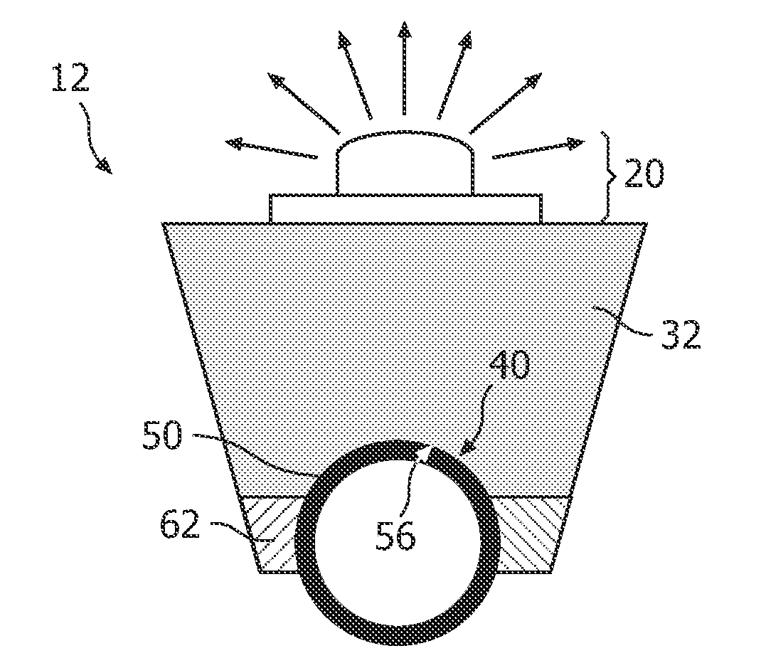
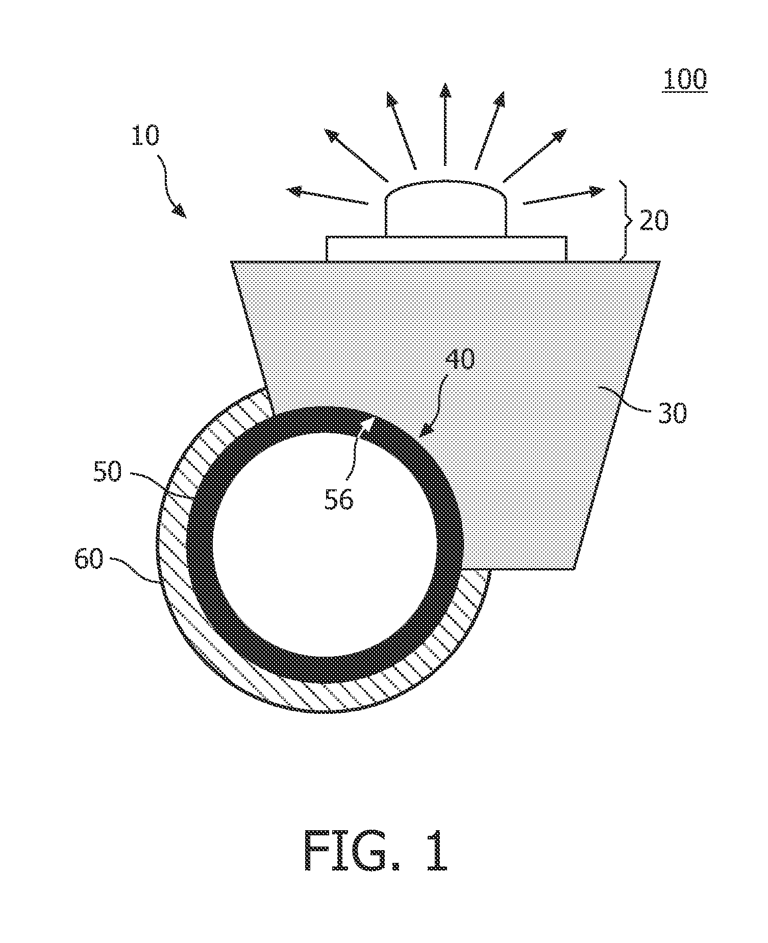
FIG. 1 shows a schematic cross-sectional view of an illumination system 100 comprising a light emitting module 10 according to the invention. The illumination system 100 comprises a cooling circuit (not shown) comprising a cooling body 50 being a cooling pipe 50. The illumination system 100 further comprises the light emitting module 10 according to the invention.

The light emitting module 10 comprises a light source 20 and a heat sink 30. The light source 20 is applied on the heat sink 30 and is thermally connected to the heat sink 30 to allow heat generated in the light source 20 to be transferred away from the light source 20. The light source 20 may, for example, be a light emitting diode 20, or a laser diode 20. The intensity of the light emitted by these light emitting diodes 20 or laser diodes 20 generally depends on the cooling of the light emitting diode 20 or the laser diode 20 and thus the cooling is essential for efficient usage of such a light source 20. Also other light...


PUM


Abstract

The invention relates to a light emitting module (10) comprising a light source (20) and a heat sink (30). The light source is thermally connected to the heat sink. The heat sink is configured to be detachably mounted on a cooling body (50), at least part of an outer wall (40) of the heat sink having a shape matching at least a part of an outer wall (56) of the cooling body to enable the transfer of heat generated by the light source to the cooling body. The effect of the measures according to the invention is that they enable the active cooling of the light emitting module to be separated from the light emitting module itself, thereby reducing the complexity of the light emitting module while still relatively easily enabling active cooling via the cooling body. The cooling body may, for example, be a cooling pipe through which a cooling fluid flows.

Description

FIELD OF THE INVENTIONThe invention relates to a light emitting module.The invention also relates to a heat sink and to an illumination system comprising the light emitting module.BACKGROUND OF THE INVENTIONLight emitting modules are known per se. They are used, inter alia, in general illumination systems, for example, for illuminating indoor and / or outdoor environments and, inter alia, in image projection systems such as beamers, projection televisions and liquid display devices. These light emitting modules are also emerging in headlight illumination systems, for example, for use in cars and motorcycles.Currently a trend in light emitting modules is to reduce the size of the modules while increasing the light output of the light emitting modules. Generally this is possible by using high pressure discharge lamps, halogen lamps and / or light emitting diodes (hereinafter also referred to as LEDs) or laser diodes as a light source. These light sources have relatively small outer dimens...

Claims


Application Information

Patent Timeline
17 Feb 2011
Publication
US20110037369A1
IPC
H01J61/52; F21K99/00
CPC
F21K9/00; F21V29/004; F21V29/02; F21V29/74; F21V29/006; F21V29/20; F21V29/73; F21Y2101/02
Inventors
VAN ELMPT, ROB FRANCISCUS MARIA