Open loop magneto-resistive magnetic field sensor

a magneto-resistive magnetic field and sensor technology, applied in the field of magnetic measurements, can solve the problems of long-term resistance shifts over time, limited circuits such as those shown in fig. 1, and the accuracy of open-loop schemes such as the one seen in fig. 1 will surely suffer over time, so as to improve the accuracy of two-sensor field measurement methods.

Active Publication Date: 2011-02-17
HEADWAY TECH INC
View PDF7 Cites 24 Cited by
  • Summary
  • Abstract
  • Description
  • Claims
  • Application Information

AI Technical Summary

Benefits of technology

[0015]A still further object of at least one embodiment of the present invention has been to improve the accuracy of two-sensor field measurement methods.

Problems solved by technology

Circuits such as that shown in FIG. 1 are limited by the fact that they use the resistance of the MR sensor directly.
Furthermore, even though, in some cases, the prior art has devised ways to deal with short-term sensitivity variations of this sort, long-term resistance shifts over time are considered to be an even more serious drawback for the FIG. 1 open-loop scheme.
This data indicates that, if changes of this type go uncorrected, open-loop schemes such as the one seen in FIG. 1 will certainly suffer accuracy degradation over time.

Method used


Image

  • Open loop magneto-resistive magnetic field sensor
  • Open loop magneto-resistive magnetic field sensor
  • Open loop magneto-resistive magnetic field sensor

Examples


embodiment 1a

Approach 1

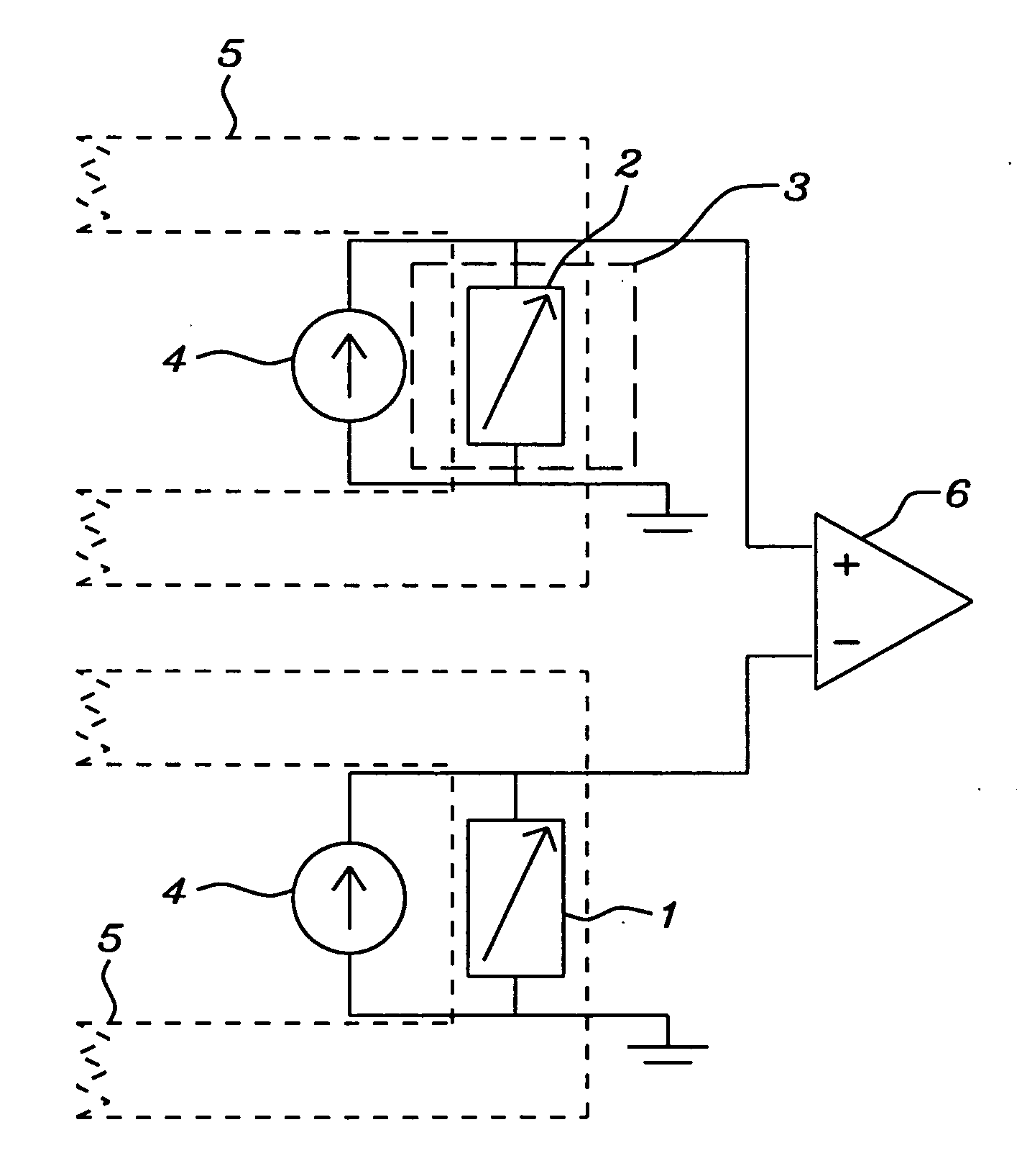
[0042]The basic elements of the device are MR sensor 1 for sensing the unknown magnetic field and MR sensor 2 for providing a zero-field reference point for sensor 1. Magnetizing coil 5 (as shown in FIG. 5) is located in close proximity to sensors 1 and 2 and produces a magnetic field at sensors 1 and 2 when coil 5 is energized by passing an electric current through it.

[0043]A more compact version of the apparatus is schematically illustrated in FIG. 6 where the predetermined magnetic field is generated by passing current through a single wire. By using thin film technology, a circuit line of this type can be located within a range of from 5 to 100 nm of both MR sensors. Additionally, said circuit line can be placed directly above, directly below, or between the two MR sensors and any microprocessor needed to compute and store data generated by the sensors can be formed at the same time.

[0044]Sensor 2, and the section of coil 5 that affects sensor 2, are shielded by magnet...

example

Referring to FIG. 5

[0046](1) Coil 5 drives both sensors 1 and 2 into saturation to generate R1max and R2max.[0047](2) Separate current sources 4 are connected to each sensor and adjusted so that Vo is dropped across each sensor.[0048](3) Without changing the current levels through sources 4, coil 5 is de-energized.[0049](4) The voltage dropped across sensor 2 is now given by V20field=(R20field / R2max)V0 since sensor 2 does not see the external field.

[0050](5) The voltage dropped across sensor 1 is now given by V1field=(R1field / R1max)V0 [0051]If sensors 1 and 2 share a common substrate, then

R10field / R1max=R20field / R2max

So, [sensor1voltage−sensor2voltage]=(R1field−R10field)V0 / R1max  (1) which is the reason for the comparator.

[0052]Note that while aging may change any or all of R1field, R10field, and R1max individually, the ratio expressed in equation (1) remains constant.

[0053]Sensor 1 and 2 can be any magneto-resistive sensor that has at least one magnetic free layer whose magnetizat...


PUM


Abstract

An apparatus and a general method to measure a magnetic field using magneto-resistive sensors in an open-loop configuration are disclosed. A key feature is the regular in-situ normalization of the sensors to compensate for the effects of sensor aging.

Description

[0001]Related application HT09-001 file Ser. No. 12 / 456,306 filed on Jun. 15, 2009, discloses methods for normalizing MR sensors to compensate for the effects of aging. It is herein incorporated, by reference, in its entirety.FIELD OF THE INVENTION[0002]The invention relates to the general field of magnetic measurements with particular reference to measuring magnetic field strength and correcting such measurements for the effects of sensor aging.BACKGROUND OF THE INVENTION[0003]When magneto-resistive (MR) sensors are used in an open-loop mode for magnetic field sensing, the field value is derived directly from the MR sensor's resistance. This requires an accurate resistance reference point and accurate estimation of the sensor sensitivity to the external field. MR sensors, especially tunneling magneto-resistance (TMR) sensors, can show large resistance changes after exposure to long term stresses that are significant enough to affect the sensing accuracy. However, when sensor resist...

Claims


Application Information

Patent Timeline
Patent Type & Authority Applications(United States)
IPC IPC(8): G01R33/09G01R35/00
CPCG01R33/098
Inventor ZHOU, YUCHENGORMAN, GRACE
Owner HEADWAY TECH INC
Why Eureka
Try Eureka