[0021]It is an object of the present invention to provide an improved control
system to control an operating room lamp by medical personnel, an
improved method for operating an operating room lamp, an improved operating room lamp, an improved
computer program, and an improved control device.
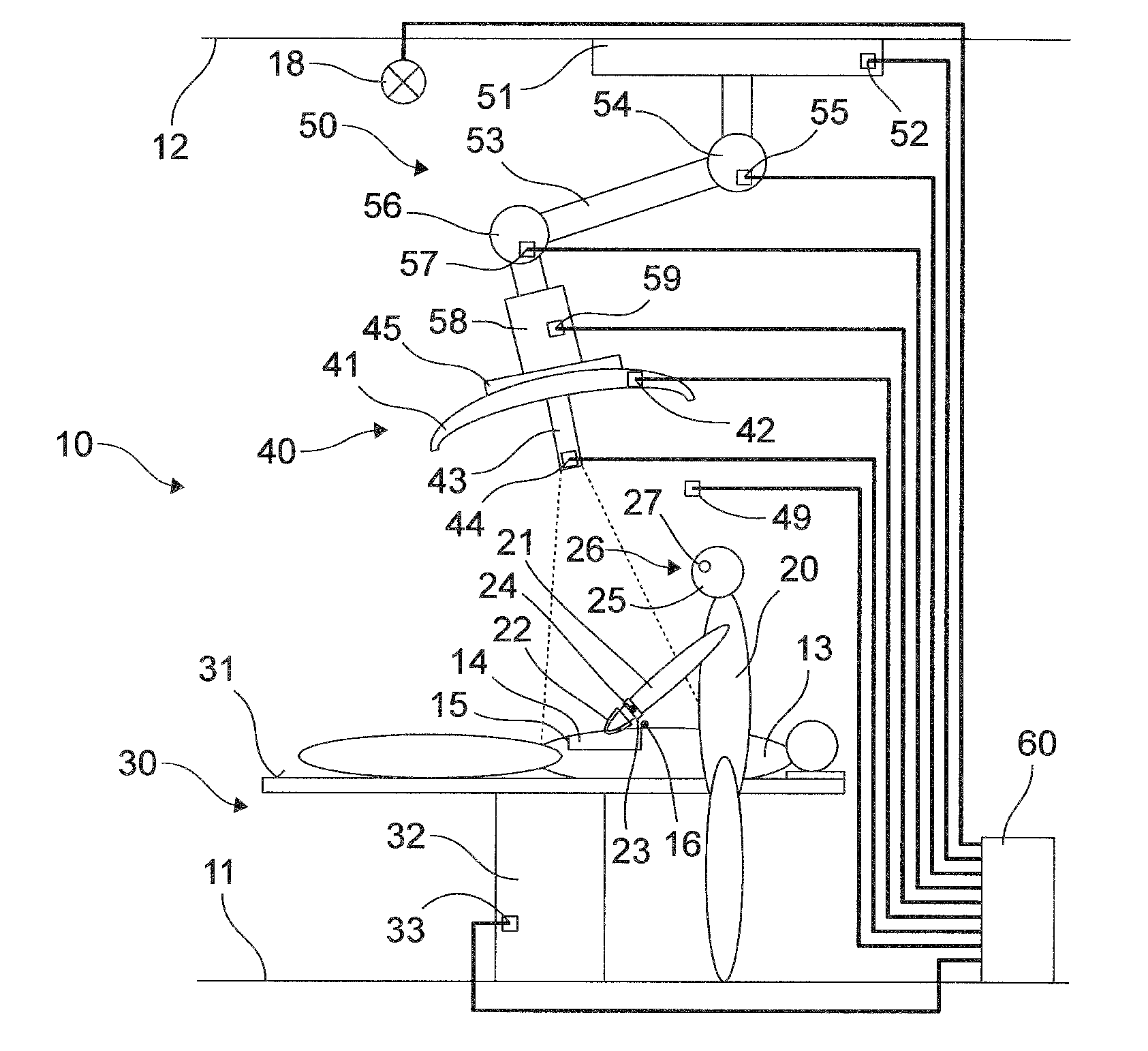
[0025]In particular with large-surface surgical sites, for example with accident victims, the present invention ensures a definite simplification and improvement of the handling. The medical personnel can to a greater extent concentrate on its actual task, since it is no longer required to concern itself with moving the operating room lamp. In particular the
cone of light emitted from the operating room lamp follows the operator's activities or those of other medical personnel and / or is adapted by the control
system to the surgical field with respect to its size and extension.
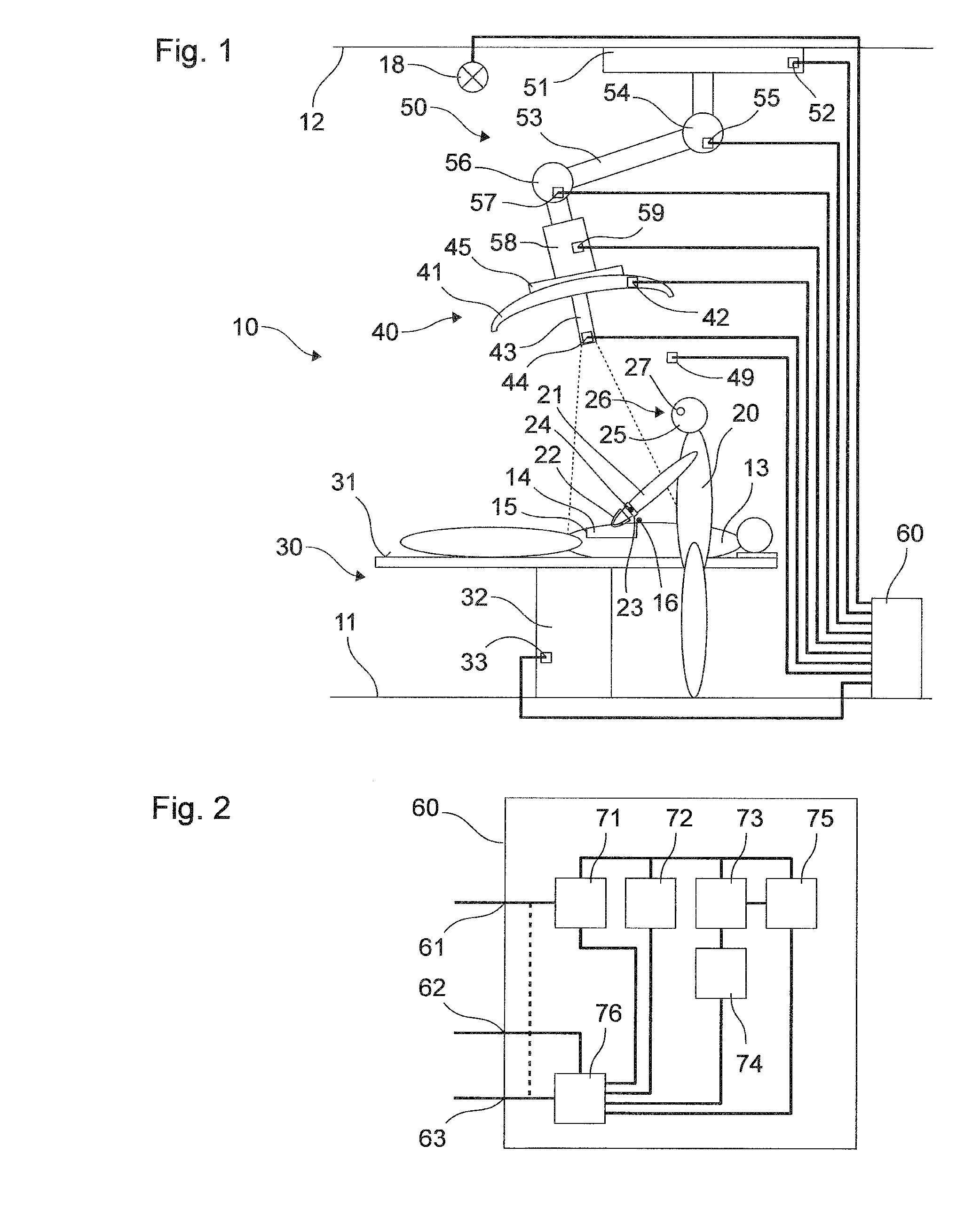
[0030]Alternatively or in addition, the control
system is configured to capture the position or positions of the medical personnel or of other bodily parts of the medical personnel. For example, the positions of the arms or head of an operator or of other medical personnel can be captured in order to generate the control
signal on the basis of these positions in such a way as to prevent light generated by the operating room lamp from being switched off. For example, the operating room lamp is displaced depending on the position or positions of the heads and arms of the medical personnel. With an operating room lamp that includes several individual lamps, a possible alternate is to switch off individual lamps whose light is shadowed by medical personnel and to switch on other individual lamps in order to maintain the lighting capacity.
[0037]This object can be, for example, an additional operating room lamp, a screen or an instrument carrier that is affixed rigidly or movably on the ceiling of the operating room or that stands on the operating room floor. The positioning
signal can be a
setpoint signal, which constitutes a desired terminal position or a change to be made in the position of the movable
operating table or of the object and that is used for instance to control the
operating table or the object, if the latter is movable. Alternatively or in addition, the positioning signal can be a status signal, which constitutes an actually existing position or an existing change in position of the movable operating tale or of the object. The control system is configured, for example, to receive the positioning signal via a
bus or another signal line from a sensor or another device or from a storage device. The storage device and the control system can be located in a common housing. For example, the position of the object with which the operating room lamp can collide is filed in the storage device. The positioning signal can continue in the generation of the control signal in order, for example, to control a simultaneous repositioning of the operating room lamp in case of a change in position of the adjustable
operating table or to avoid a collision of the operating room lamp with the object.
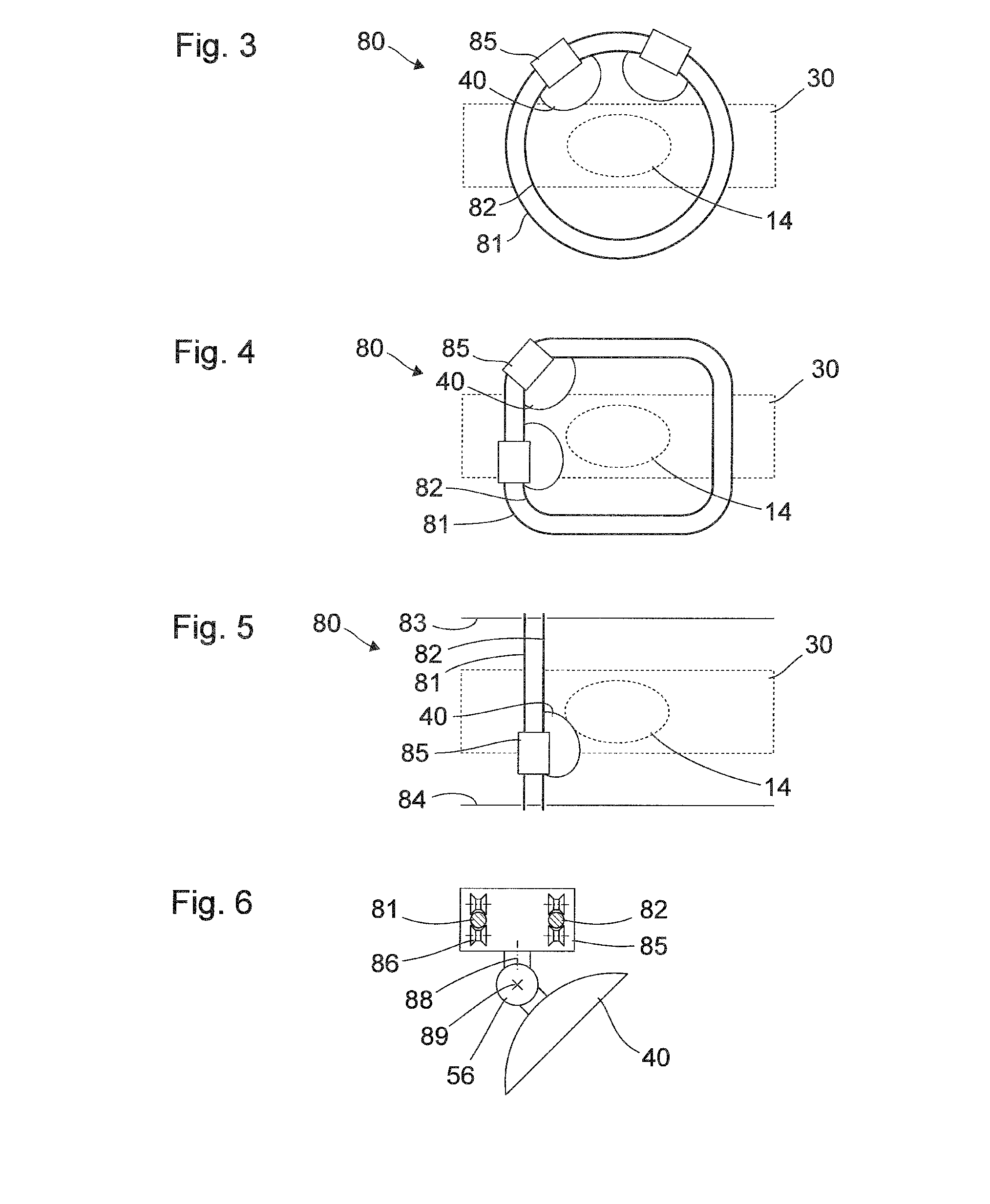
[0049]The track device of the operating
lighting system can be configured in such a way that the entire operating room
lighting system forms a low structural height. Consequently the operating
lighting system can also be installed in a low operating room, in which the use of a conventional lighting arm with several joints is a
disadvantage, because the operating room lamp hangs too low and / or restricts the mobility of the
medical staff. Also in an operating room with standard height a low structural height can be advantageous because the operating room lamp can be positioned at greater height and thus it disturbs the medical personnel less or not at all. In addition, further apparatuses such as image screens or other devices can be positioned more freely if the operating room lamp is placed at a greater height.
[0062]The positioning signal can be received by a
bus or another signal line from a sensor or another device or from a storage facility, such that the storage facility and the control system can be located in a common housing. As shown above in connection with the control system, this object is for example an additional operating room lamp, a screen, or an instrument platform, which is mounted rigidly or movably on the ceiling of the operating room or stands on the floor of the operating room. As also discussed above, the positioning signal can be a status symbol or a
setpoint signal. Consequently, with a change in position of the movable operating table, a simultaneous readjustment of the operating room lamp can be controlled and / or a collision of the operating room lamp with another object can be prevented.

