Photochromic optical article

a photochromic and optical article technology, applied in the field of optical articles, can solve the problems of not being the best carrier to allow particular photochromatic dyes to achieve sufficiently fast color change and color fading rates, and inability to be used, etc., and achieve the effect of enhancing photochromic properties

Inactive Publication Date: 2011-02-17
DARWIN OPTICAL
View PDF3 Cites 85 Cited by
  • Summary
  • Abstract
  • Description
  • Claims
  • Application Information

AI Technical Summary

Benefits of technology

[0010]Therefore, the object of the present invention is to provide a photochromic optical article with enhanced photochromic properties.

Problems solved by technology

1. In one conventional method, a photochromic dye(s) is directly mixed with a material of a target body, such as an eyeglass lens, so that the target body contains the photochromic dye(s). Commonly used materials for the eyeglass lens are allyl diglycol carbonate (CR-39), polycarbonate, and other polymeric materials with high refractive indices. A disadvantage of this method is that it is unable to be used where the material of the target body is not suitable for use as a carrier for the photochromic dye(s). Even if the material of the target body can be a photochromic dye carrier, it may not be the best carrier to allow particular photochromatic dye(s) to achieve sufficiently fast rates of color change and color fading, a sufficient darkness, or satisfactory color.
2. In another conventional method, a suitable polymer, such as cellulose acetate butyrate, is selected as a carrier, and a photochromic dye(s) is added to the selected polymer to make a laminate. The laminate is then adhered to a polycarbonate lens to form a photochromic lens. Although such a technique can resolve the drawback of the aforementioned method that involves directly mixing photochromic dye(s) with a target body, the steps involved therein are complicated so that a high manufacturing cost and a high defect rate result.
3. To resolve the aforesaid drawbacks, the use of a coating process to form a photochromic layer on a surface of a lens is developed. Aside from allowing selection of a good carrier for the photochromic dye(s), use of the techniques disclosed in these patents is such that the manufacturing process is simplified, and the manufacturing cost is minimized. However, while the original color prior to color change and the resulting color after color change are important factors that determine whether a photochromic article is acceptable or not in the market, a single photochromic dye, as is used in these patents, cannot ensure that such color transformation characteristics will be achieved.
4. Referring to FIG. 1, a photochromic article 9 includes two different photochromic dyes (A, B). A polymeric material is first selected as a carrier (X), after which a photochromic dye (A) and a photochromic dye (B) are mixed with the polymer or prepolymer carrier (X). The carrier (X) is then coated on a substrate 91 by a coating process. After curing, a single photochromic layer 92 is formed on the substrate 91. Since a photochromic dye demonstrates different photochromic properties in different carriers, the photochromic dyes (A, B) in the photochromic layer 92 may therefore demonstrate different photochromic properties after mixing with the carrier (X). Hence, the carrier (X) cannot be a suitable carrier for both of the photochromic dyes (A) and (B).
5. Referring to FIG. 2, a conventional method to increase the activated color intensity of the photochromic article 9 involves increasing the thickness of the photochromic layer 92 or increasing a weight ratio of photochromic dye to carrier. However, a coating process cannot produce a very thick coating layer. Further, if the coating layer is very thick, it easily shrinks during a curing process so that the coating layer will be uneven or produces an internal stress. Moreover, the weight ratio of photochromic dye to carrier can be increased only within a limited range. If the weight ratio of photochromic dye to carrier is excessively large, not only is it not possible to intensify the color, any color change at all may be rendered difficult.

Method used


Image

  • Photochromic optical article
  • Photochromic optical article
  • Photochromic optical article

Examples


Embodiment Construction

[0018]Before the present invention is described in greater detail, it should be noted that the same reference numerals have been used to denote like elements throughout the specification.

[0019]The photochromic optical article of the present invention may be a lens (such as an eyeglass lens), a screen, a window, a protective plate, etc., and may be an element having a special function, such as a photochromic film / coating, a polarized lens, or a colored lens. The photochromic optical article of the present invention is not limited to the aforesaid disclosure.

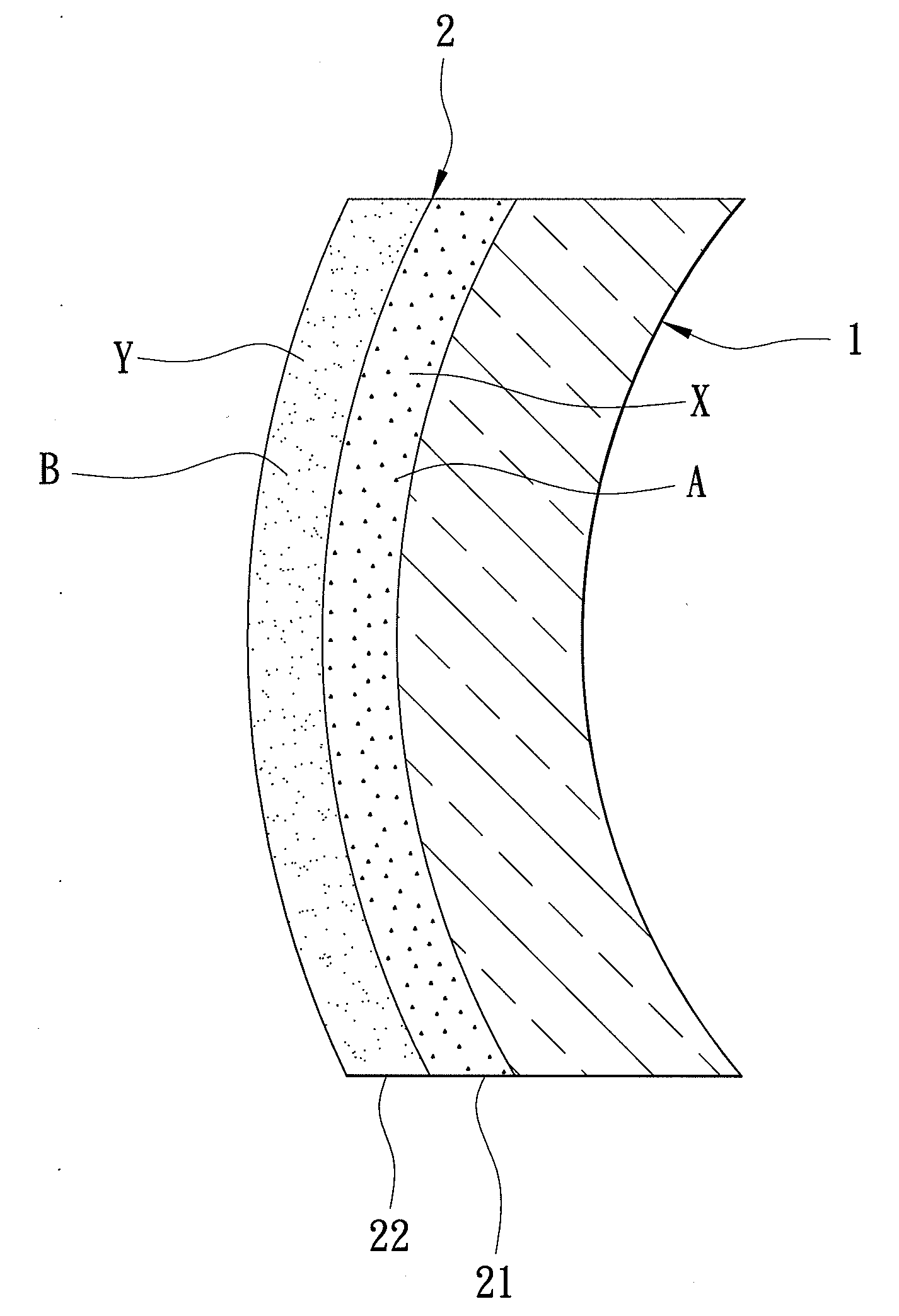
[0020]Referring to FIG. 3, a photochromic optical article according to the first preferred embodiment of the present invention is shown to comprise a substrate 1 and a photochromic coating 2.

[0021]The substrate 1 is a transparent or semi-transparent optical element, and may be made of a glass material, a ceramic material, or a plastic material, such as polycarbonate (PC), polymethylmethacrylate (PMMA), allyl diglycol carbonate res...


PUM

PropertyMeasurementUnit
photochromicaaaaaaaaaa
weight ratioaaaaaaaaaa
photochromic effectaaaaaaaaaa

Abstract

A photochromic optical article comprises a substrate, and a photochromic coating coated on an outer surface of the substrate and having at least two photochromic layers. Each of the photochromic layers has a composition that contains a carrier and at least one photochromic dye. The compositions of the photochromic layers are different from each other.

Description

BACKGROUND OF THE INVENTION[0001]1. Field of the Invention[0002]This invention relates to an optical article, more particularly to a photochromic optical article.[0003]2. Description of the Related Art [0004]A carrier containing a photochromic dye(s) can undergo change in color when exposed to light radiation, such as UV radiation or sunlight, and returns to its original color when removed from the light radiation. This phenomenon is known as a photochromic effect. In general, the same photochromic dye(s) present in different carriers will produce different colors, different activated intensities, different color activating and fading rates, etc. Further, different carriers have different capacities for mixing with the same photochromic dye(s) so that a dye-to-carrier weight ratio varies for different carriers and the same photochromic dye(s). Methods of providing a photochromic effect in the prior art have the following characteristics and drawbacks:[0005]1. In one conventional met...

Claims


Application Information

Patent Timeline
Patent Type & Authority Applications(United States)
IPC IPC(8): G02F1/23G02B1/10
CPCG02B5/23G02C2202/16G02C7/102
Inventor WANG, YUN-CHENGWANG, YI-TANG
Owner DARWIN OPTICAL
Why Eureka
Try Eureka