After application anchor bolt

a post-installation anchor and bolt technology, applied in the field of anchor bolts, can solve the problems of only insufficient anchoring strength of post-installation anchors, and achieve the effect of facilitating expansion and sufficient anchoring strength

Active Publication Date: 2011-02-17
TAISEI KOUGYOU
View PDF9 Cites 6 Cited by
  • Summary
  • Abstract
  • Description
  • Claims
  • Application Information

AI Technical Summary

Benefits of technology

[0012]According to one embodiment of the post-installed anchor, the fixation member has at least four cuts, and the expansion end is divided into multiple expansion pieces by the at least four cuts to have a shape widened toward an edge of the expansion end. The post-installed anchor of this embodiment has the expansion end divided into four or a greater number of expansion pieces, thus facilitating the expansion.
[0013]According to one embodiment of the post-installed anchor, at least one of the multiple expansion pieces of the expansion end divided by the at least four cuts is formed in a shape that prevents an edge of the sleeve in proximity to the fixation member from entering deep inside the expansion end in the course of inserting the post-installed anchor into the pilot hole. This arrangement effectively prevents the sleeve from being stuck in the expansion end in the course of insertion of the post-installed anchor into the pilot hole and from interfering with further insertion of the post-installed anchor.
[0014]According to one embodiment of the post-installed anchor, the expansion end of the fixation member has a longer length in an axial direction than a length of the threaded end of the fixation member screwed to the threaded end of the bolt body. This arrangement has the sufficient length of the expansion end and allows for deformation of the expansion end accompanied induced by the rotation of the bolt body and the sufficient bite of the expansion end into the inner wall of the pilot hole.
[0015]According to another aspect of the invention, there is provided a post-installed anchor driven in a pilot hole to be securely fixed and structured by a simple combination of a bolt body, a sleeve, and a fixation member. At least two bolt bodies of different lengths and at least two sleeves of different lengths are provided. Assembling one selected bolt body and one or multiple selected sleeves readily gives a post-installed anchor having a different whole length. In the post-installed anchor according to this aspect of the invention, a fixation member is structured to have a threaded end screwed to a threaded end of the bolt body with the sleeve fit thereon and an expansion end arranged in proximity to the sleeve. With a movement of the fixation member toward a head of the bolt body, which is induced by rotation of the bolt body, an edge of the sleeve presses open and extends outward the expansion end of the fixation member. The post-installed anchor of this arrangement has the sufficient anchoring strength.

Problems solved by technology

Post-installed anchors may have only insufficient anchoring strength, due to the characteristic of post construction.

Method used


Image

  • After application anchor bolt
  • After application anchor bolt
  • After application anchor bolt

Examples


first embodiment

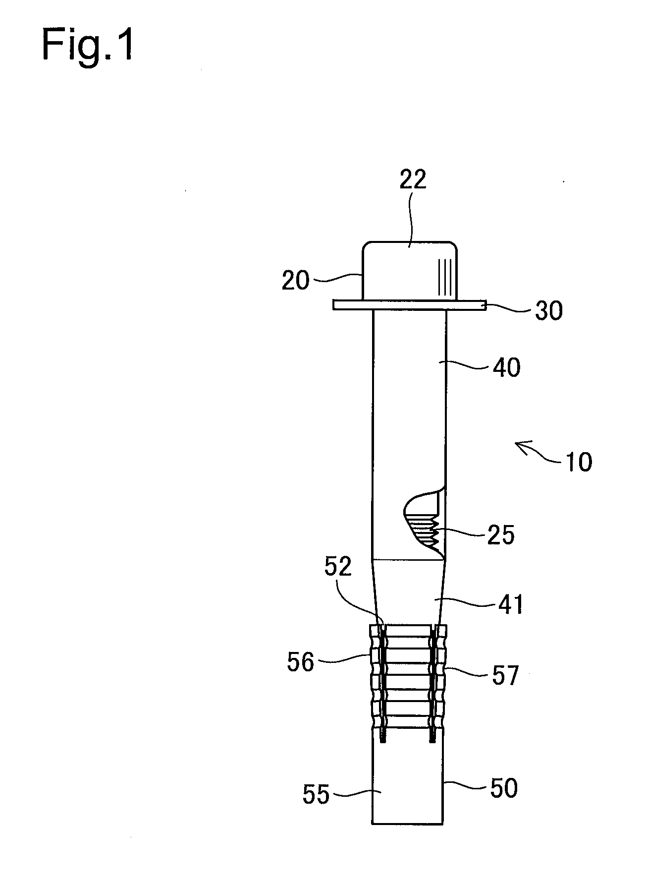
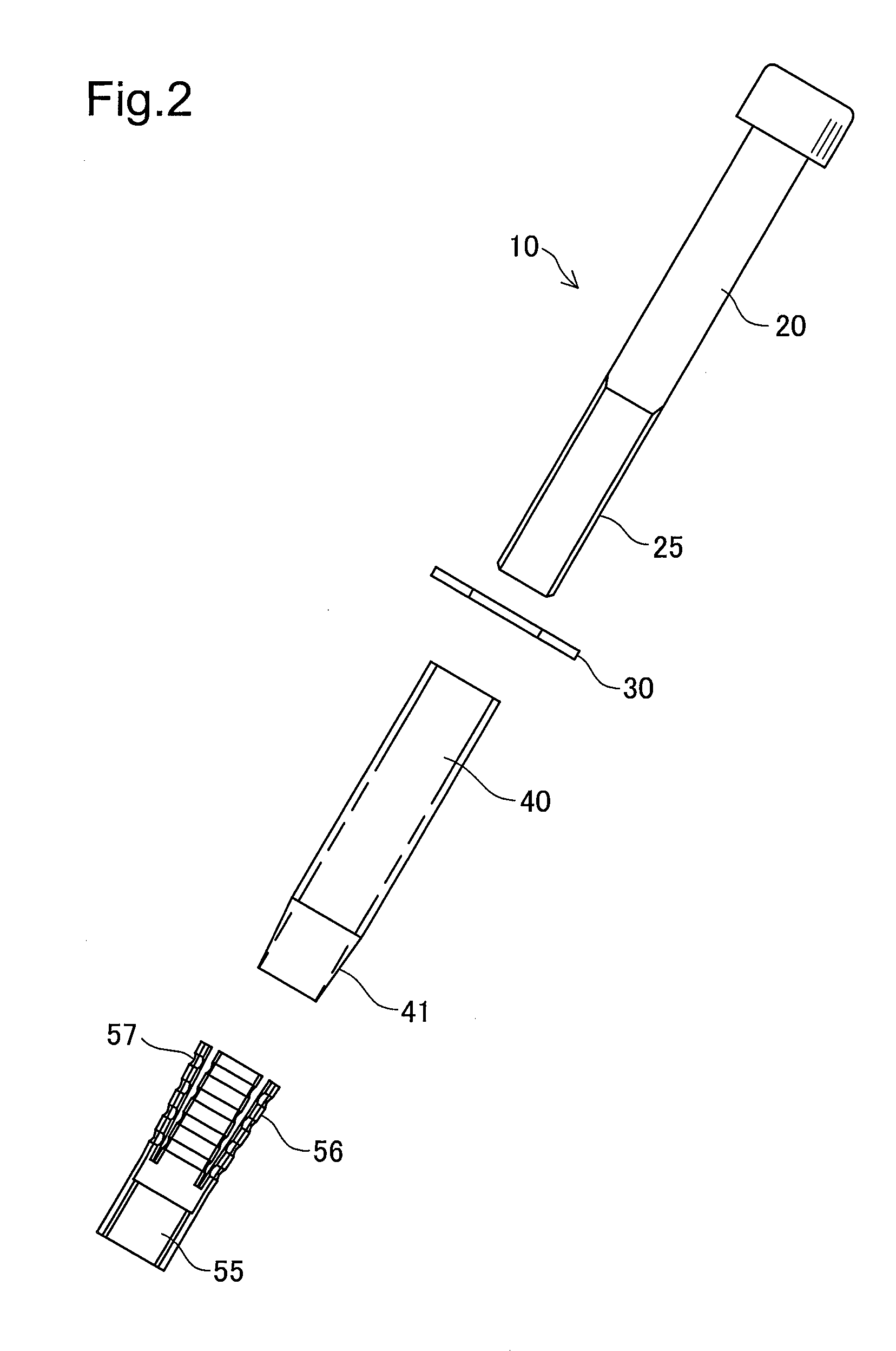
[0028]One embodiment of the invention is described below. FIG. 1 is an explanatory diagrammatic representation of the structure of a post-installed anchor 10 according to the invention. The post-installed anchor 10 is shown in an assembled state in FIG. 1. FIG. 2 is an explanatory diagrammatic representation of the post-installed anchor 10 in a disassembled state.

[0029]As shown in FIGS. 1 and 2, the post-installed anchor 10 of the first embodiment includes a bolt body 20, a washer 30 attached first to the bolt body 20, a sleeve 40 having a tapered face on one end, and a fixation member 50 screwed to the bolt body 20. An assembling procedure sequentially attaches the washer 30 to the bolt body 20, fits the sleeve 40 on the bolt body 20 with a tapered face 41 located in proximity to one end of the bolt body 20, and screws an internal threaded end 55 of the fixation member 50 to an external threaded end 24 of the bolt body 20 in such a manner as to locate an expansion end 56 in proximi...

second embodiment

[0046]In the post-installed anchor 100 or 110 of the second embodiment, the sleeve 140 consists of multiple members. Combining sleeves of different lengths readily gives post-installed anchors 100 or 110 of various lengths. Typical examples include a combination of two shorter sleeves 140a (FIG. 10A), a combination of first and second sleeves 140a and 140b of different lengths (FIG. 10B), and a combination of two longer sleeves 140b (FIG. 10C). Providing only two types of sleeves having different lengths (140a and 140b) enables the manufacturer to produce five different lengths of post-installed anchors 100 (110) including those with only one shorter sleeve and with only one longer sleeve. In another application, only one type of sleeve having a shorter length may be provided, and varying the number of sleeves may give different lengths of post-installed anchors.

[0047]The post-installed anchor 100 (110) of the second embodiment has the sufficiently high tensile strength by the simpl...

third embodiment

[0050]In the post-installed anchor 200 of the third embodiment shown in FIG. 11, the shank member 240 of the bolt body 220 other than the tapered portion 241 has a fixed outer diameter. As long as the shank member 240 has the tapered portion 241 and causes the expansion end 256 of the fixation member 250 to be press fit in and bite into an inner wall of an installation hole, the shank member 240 may have a decreasing outer diameter. This arrangement desirably reduces the total weight of the post-installed anchor 200.

[0051]In a post-installed anchor 300 according to a fourth embodiment of the invention shown in FIG. 12, a washer 330 may also be integrated with a bolt body 320. As in the third embodiment, in the post-installed anchor 300 of the fourth embodiment, a shank member 340 functions as a large-diameter member like the sleeve. The post-installed anchor 300 with a fixation member 350 attached thereto is inserted into an installation hole 90. With rotation of a bolt body 320, an...


PUM


Abstract

The present invention relates to an anchor bolt and more specifically pertains to a post-installed anchor that is securely anchored to, for example, an existing concrete floor. The post-installed anchor has a sleeve fit on a bolt body and a fixation member arranged on an edge of the bolt body and screwed to a threaded end of the bolt body. The fixation member has an internal threaded end and an expansion end. The expansion end is divided into four expansion pieces by slits. The expansion pieces are arranged to face a head of the bolt body and are slightly widened toward the head of the bolt body. One end of the sleeve forms a tapered face. After insertion of the post-installed anchor into a pilot hole (installation hole) bored in the concrete floor, as the bolt body rotates, the fixation member screwed to the bolt body moves toward the sleeve. This movement causes the expansion end of the fixation member to ride on the tapered face of the sleeve and to be pressed open and extended outward. The expansion pieces of the expansion end are then buckled and bite into an inner circumferential face of the installation hole, so that the post-installed anchor is securely fixed to the installation hole.

Description

TECHNICAL FIELD[0001]The present invention relates to an anchor bolt and more specifically pertains to a post-installed anchor that is securely anchored to an existing floor surface or an existing wall surface made of, for example, concrete.BACKGROUND ART[0002]Anchor bolts are generally embedded in concrete for the purpose of fixation of a structural member (timber or steel) or equipment. There is another type of anchor bolt that is attached to an existing concrete floor. This type of anchor bolt used for fixation after construction is called ‘after application anchor bolt’ or ‘post-installed anchor’.[0003]For attachment of the post-installed anchor in the existing concrete floor, a pilot hole of a predetermined depth is opened, and the post-installed anchor is inserted into and fixed to the pilot hole. There are two different types of fixation, chemical-type fixation and sleeve-type fixation. The chemical-type fixation fills the pilot hole with an adhesive and drives the anchor int...

Claims


Application Information

Patent Timeline
Patent Type & Authority Applications(United States)
IPC IPC(8): F16B39/00F16B29/00F16B35/00
CPCF16B13/066
Inventor ITO, TOSHIHARUHIJIKATA, SEIJI
Owner TAISEI KOUGYOU
Why Eureka
Try Eureka