Turbine, in particular for an exhaust gas turbocharger, and exhaust gas turbocharger

a technology of exhaust gas and turbocharger, which is applied in the direction of positive displacement liquid engine, mechanical apparatus, pumps, etc., can solve the problems of no longer being able to adjust or actuate the guide vanes, the variable turbine geometry is no longer functional, and the guide vanes cannot be adjusted or actuated, so as to achieve simple and cost-effective assembly and maintenance, the effect of simple turbin

Active Publication Date: 2011-02-17
BOSCH MAHLE TURBO SYST GMBH & CO KG
View PDF9 Cites 27 Cited by
  • Summary
  • Abstract
  • Description
  • Claims
  • Application Information

AI Technical Summary

Benefits of technology

[0025]Furthermore, it is provided that the turbine comprises at least one pin connection for positioning and/or aligning the guide apparatus, the guide vane bearing ring and/or the guide vane cover ring on the housing. Preferably the pin connection comprises at least one pin which is inserted in a pin reception of the guide apparatus or one of its components and/or the housing. By using one or a plurality of pin connections the assembly of the turbine remains simple and cost-effective.
[0026]Practically, at least one pin reception is designed as elongated hole so that relocating or moving of the guide apparatus, the guide vane bearing ring or t

Problems solved by technology

Any deformation of the housing for the above mentioned reasons in this case will result in high friction values between the guide vanes and the housing in the event of an adjustment or a change of the vane angle of the guide vanes.
It this stresses and deformations of the housings are sufficiently high, the guide vanes can no longer be adjusted or actuated.
The variable turbine geometry is thus no longer functional.
The guide vanes which in operati

Method used


Image

  • Turbine, in particular for an exhaust gas turbocharger, and exhaust gas turbocharger
  • Turbine, in particular for an exhaust gas turbocharger, and exhaust gas turbocharger
  • Turbine, in particular for an exhaust gas turbocharger, and exhaust gas turbocharger

Examples


Embodiment Construction

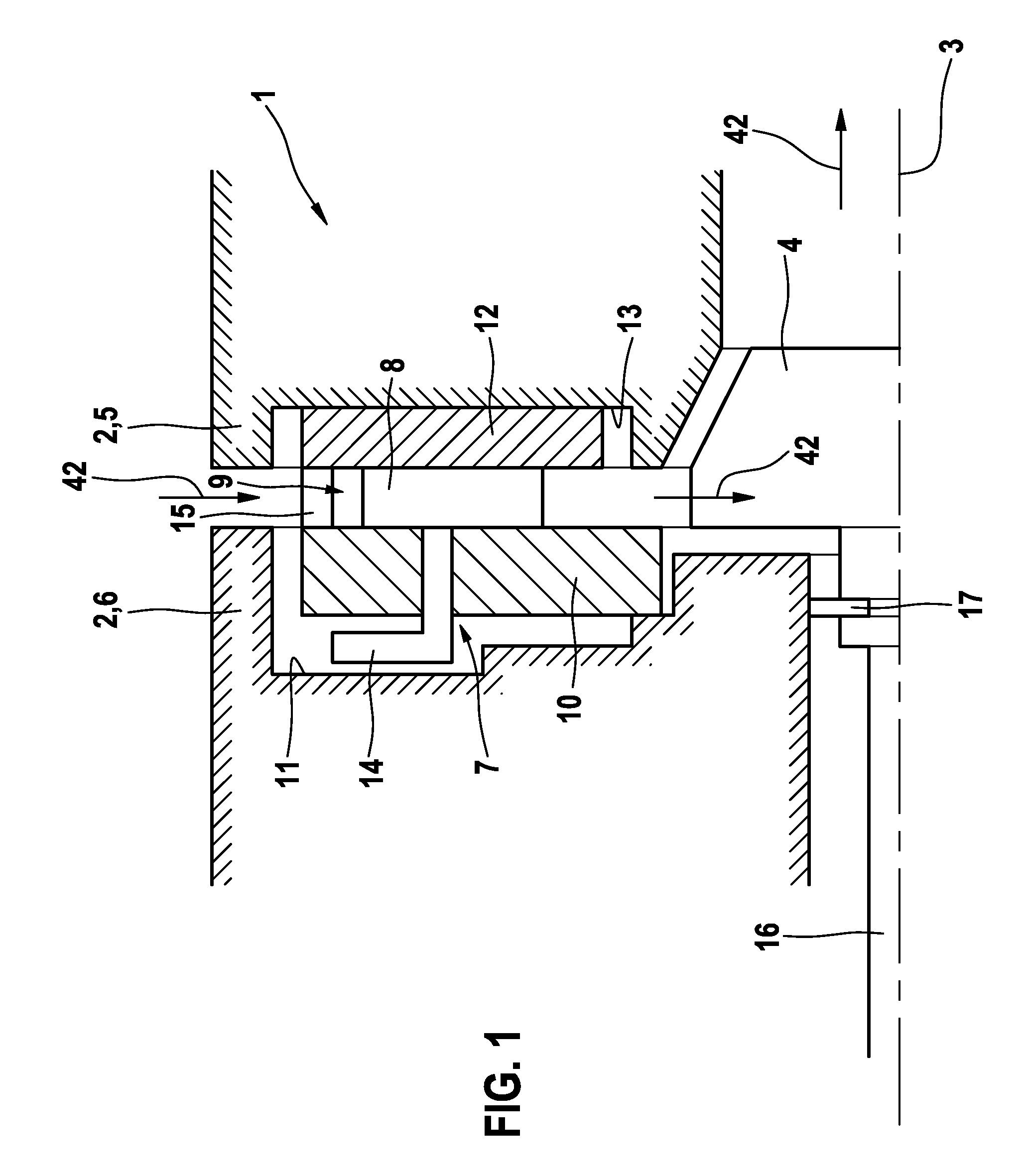
[0056]FIG. 1 shows a turbine 1 of an exhaust gas turbocharger for a motor vehicle which is not shown in more detail here in a schematic sectional representation. The turbine 1 comprises a turbine rotor 4 rotatably mounted about a rotational axis 3 in a housing 2, wherein only the part above the rotational axis 3 is shown. The housing 2 of the turbine 1 is designed in two parts, wherein one part forms a turbine housing 5 and the other part a bearing housing 6, wherein the bearing housing 6—with respect to the rotational axis 3—axially follows the turbine housing 5, and between the turbine housing 5 and the bearing housing 6 a flow cross section for a medium driving the turbine rotor is formed. The medium, in the present exemplary embodiment the exhaust gas of the combustion engine, can radially flow into the housing 2 to the turbine rotor 4 and once it has performed work on the turbine rotor 4, again axially exists from the turbine housing 5 as indicated by the arrows 42.

[0057]In the...


PUM


Abstract

An exhaust gas turbocharger, comprising: a turbine rotor rotatably mounted in a housing, which is associated with at least one guide apparatus forming a radial inlet channel, wherein the guide apparatus includes at least one of a guide vane bearing ring, a plurality of guide vanes radially surrounding the turbine rotor and located in the inlet channel and a guide vane cover ring. The inlet channel is axially delimited by the guide vane bearing ring and the guide vane cover ring wherein the guide vane bearing ring and the guide vane cover ring are moveably mounted at least one of axially and radially relative to each other and to the housing. The guide apparatus is subjected to at least one of an axial and radial preload, wherein a line of axial preload flux runs through the guide apparatus substantially parallel to the rotational axis of the turbine rotor.

Description

[0001]The invention relates to a turbine, in particular for an exhaust gas turbocharger with a turbine rotor rotatably mounted in a housing, which is associated with at least one guide apparatus forming a radial inlet channel for a medium driving the turbine rotor.[0002]Furthermore, the invention relates to an exhaust gas turbocharger, in particular for a motor vehicle having a turbine and a compressor which are operationally connected with each other mechanically.PRIOR ART[0003]Turbines, in particular in motor vehicle construction, are known from the prior art in connection with gas turbochargers having a turbine rotor rotatably mounted in a housing, which is associated with a least one guide apparatus forming a radial inlet channel for a medium driving the turbine rotor. In motor vehicle construction turbochargers are used to increase the power and the rotational moment of a combustion engine. The turbine more specifically the turbine rotor of the turbine of such an exhaust gas tu...

Claims


Application Information

Patent Timeline
IPC IPC(8): F04B17/00
CPCF01D17/165F02C6/12F05D2220/40F01D25/246F05D2250/42F01D9/04F05D2230/642
Inventor FLEIG, CLAUSSTEIN, MATTHIASTRIES, TIMOWENGERT, ANDREAS
Owner BOSCH MAHLE TURBO SYST GMBH & CO KG
Why Eureka
Try Eureka