Wind Energy Conversion Apparatus

a technology of wind energy and conversion apparatus, which is applied in the direction of machines/engines, electric generator control, greenhouse gas reduction, etc., can solve the problems of significant power line loss, reduce maintenance costs, reduce equipment stress, and reduce power transmission components

Inactive Publication Date: 2011-02-24
KELLY SAMUEL THOMAS
View PDF8 Cites 39 Cited by
  • Summary
  • Abstract
  • Description
  • Claims
  • Application Information

AI Technical Summary

Benefits of technology

[0029]The free running pump operatively engaged to the blades of the windmill, instead of a conventional turbine, reduces the stresses on power transmission components caused by lulls and gusts in the wind. This is a particularly taxing element of conventional wind farms using turbines for power generation. By reducing equipment stresses, the maintenance costs are reduced and equipment life is increased.
[0030]Additionally, since the wind in any given locale is unpredictable, and in general blows as much in times of low demand as it does at times of high demand, the power conventional wind turbines produce in these off times is often less value than when demand is high. This is because there is no economical means to store electrical energy in large volume for insertion to the grid at more opportune time frames. The device and method herein provide a means to store the energy produced at inopportune and communicate it to the grid as needed for peaks or when prices are higher. Thus the storage element of the system helps balance a supply and demand mismatch by saving electric power when it is less needed, to be inserted into the power grid at times when it is needed more.
[0031]Such large volume wind energy storage is accomplished by employing

Problems solved by technology

These “good” wind locations are often far from cities where the power is needed, and as a consequen

Method used


Image

  • Wind Energy Conversion Apparatus
  • Wind Energy Conversion Apparatus
  • Wind Energy Conversion Apparatus

Examples


Embodiment Construction

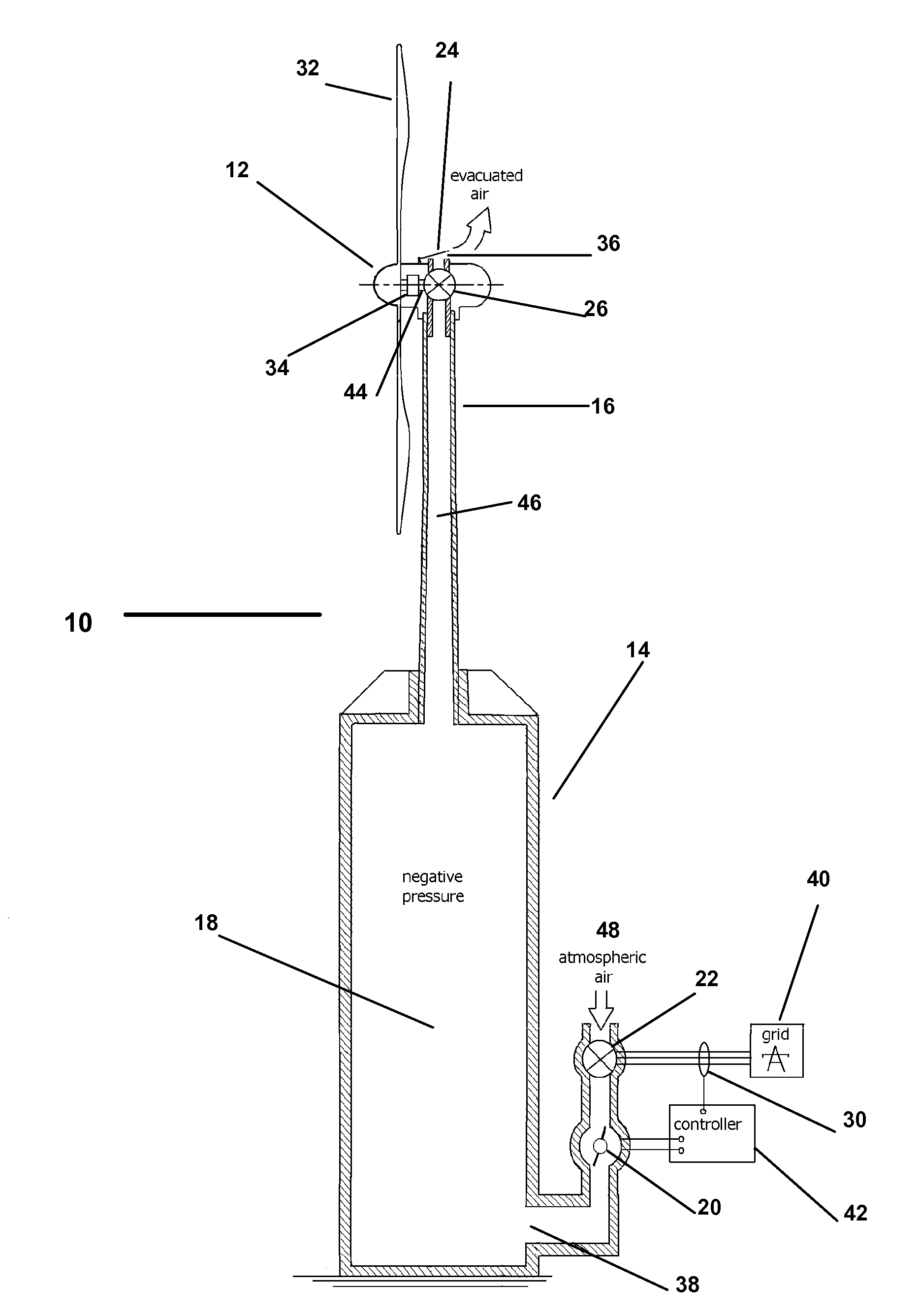
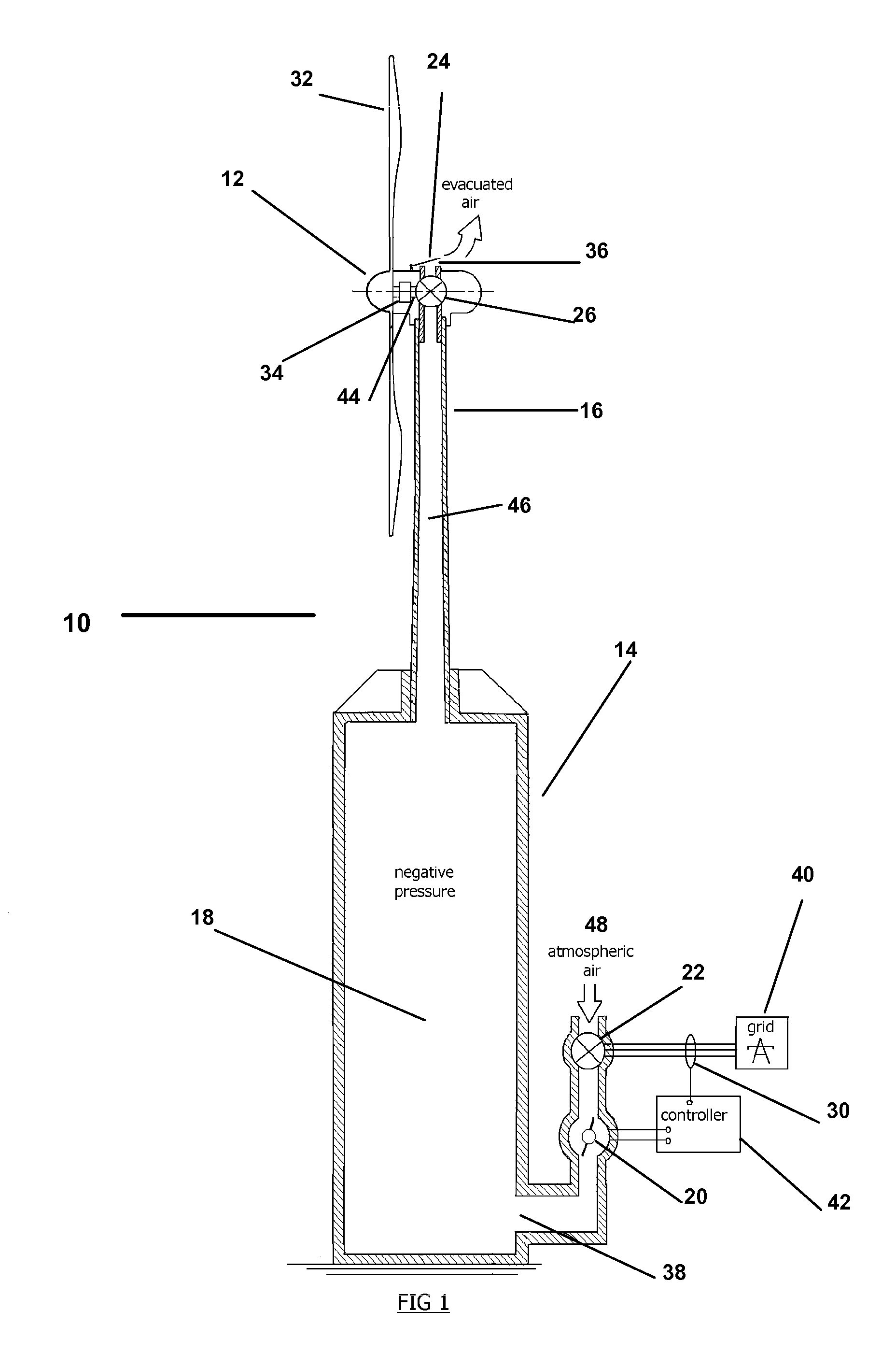
[0042]Referring now to the drawings depicting the method and device 10 in FIGS. 1-4, wherein similar parts are identified by like reference numerals, as noted FIG. 1 illustrates the system of the invention wherein a windmill assembly 12 which incorporates wind vanes 32 disposed to intercept prevailing winds. Also shown are a geared reduction component 34 and a means for pumping air or evacuating air from a closed cavity 18, such as an air pump 24.

[0043]The pump 24, is operatively engaged through a conduit 46 to evacuate air from an airtight reservoir means, such as the cavity 18 formed within the silo structure 14 in a preferred mode of the device herein. Those skilled in the art will realize that other cavities 18 or means for storage of negative air pressure might also be placed in communication with the pump 24 driven by the windmill assembly 12 or a plurality of such cavities 18 may be made available for evacuation of air therefrom. Consequently, the displayed cavity 18 is there...


PUM


Abstract

An apparatus and method to efficiently convert erratic wind energy to a source of reliable standard AC electrical power by means of a complex tower-mounted windmill operatively engaged to power a pump. The pump in a sealed communication with a chamber evacuates air from the chamber to store the wind-generated energy as potential energy in the form of a pressure differential with ambient atmosphere. Regulated air inflow into the evacuated chamber is employed to drive a generator to produce electric power which is synchronized with the grid on demand.

Description

FIELD OF THE INVENTION[0001]The device and method of employment thereof herein described relates to windmills. More particularly it relates to a novel construction and method of operation of a windmill energy generation field allowing for a variable mount to the turbine and blades and the storage of wind energy in a vacuum which may be accessed by the user or energy provider as needed to generate electrical power.BACKGROUND[0002]The industry providing renewable energy and wind derived energy in particular, is growing steadily both in the U.S. and worldwide. In the United States, public policy is continuing to evolve toward the employment of renewable energy sources for electrical power generation rather than using fossil fuels and water power from dams, as has been done in recent decades.[0003]Many states, as well as the Federal Government, encourage the use and development of renewable power sources through grants and available funds for energy development projects. Ever increasing...

Claims


Application Information

Patent Timeline
IPC IPC(8): F03D9/02
CPCF03D9/028Y02E60/15Y02E10/72F05B2220/704F03D9/17Y02E60/16Y02P80/10Y02E70/30F03D9/255F03D9/28
Inventor KELLY, SAMUEL THOMAS
Owner KELLY SAMUEL THOMAS
Why Eureka
Try Eureka