
Battery backup system with sleep mode

a battery backup and sleep mode technology, applied in the field of battery backup systems, can solve the problems of ineffective implementation of sleep command and high cost of preventative charging, and achieve the effects of minimizing discharge, maximizing calendar life, and improving shelf life of stored battery packs

Inactive Publication Date: 2011-02-24
AVAGO TECH INT SALES PTE LTD
View PDF11 Cites 13 Cited by
  • Summary
  • Abstract
  • Description
  • Claims
  • Application Information

AI Technical Summary

Benefits of technology

The present invention is about a device that includes a charger circuit and a control circuit. The charger circuit generates power down signals based on a charge signal, a supply voltage, and a control signal. The control circuit generates the charge signals based on a battery signal. The device can enter a power down state when the control circuit initiates it. The invention aims to provide a battery backup system that improves the shelf life of stored battery packs, minimizes discharge from in-system storage to maximize calendar life, and allows a device powered by the system to off load the contents of a cache memory to permanent storage prior to a power down of the system.

Problems solved by technology

Such preventative charging is costly.
The sleep command of a typical charger is not effective when implemented on a two pack system.

Method used


Image

  • Battery backup system with sleep mode
  • Battery backup system with sleep mode
  • Battery backup system with sleep mode

Examples


Embodiment Construction

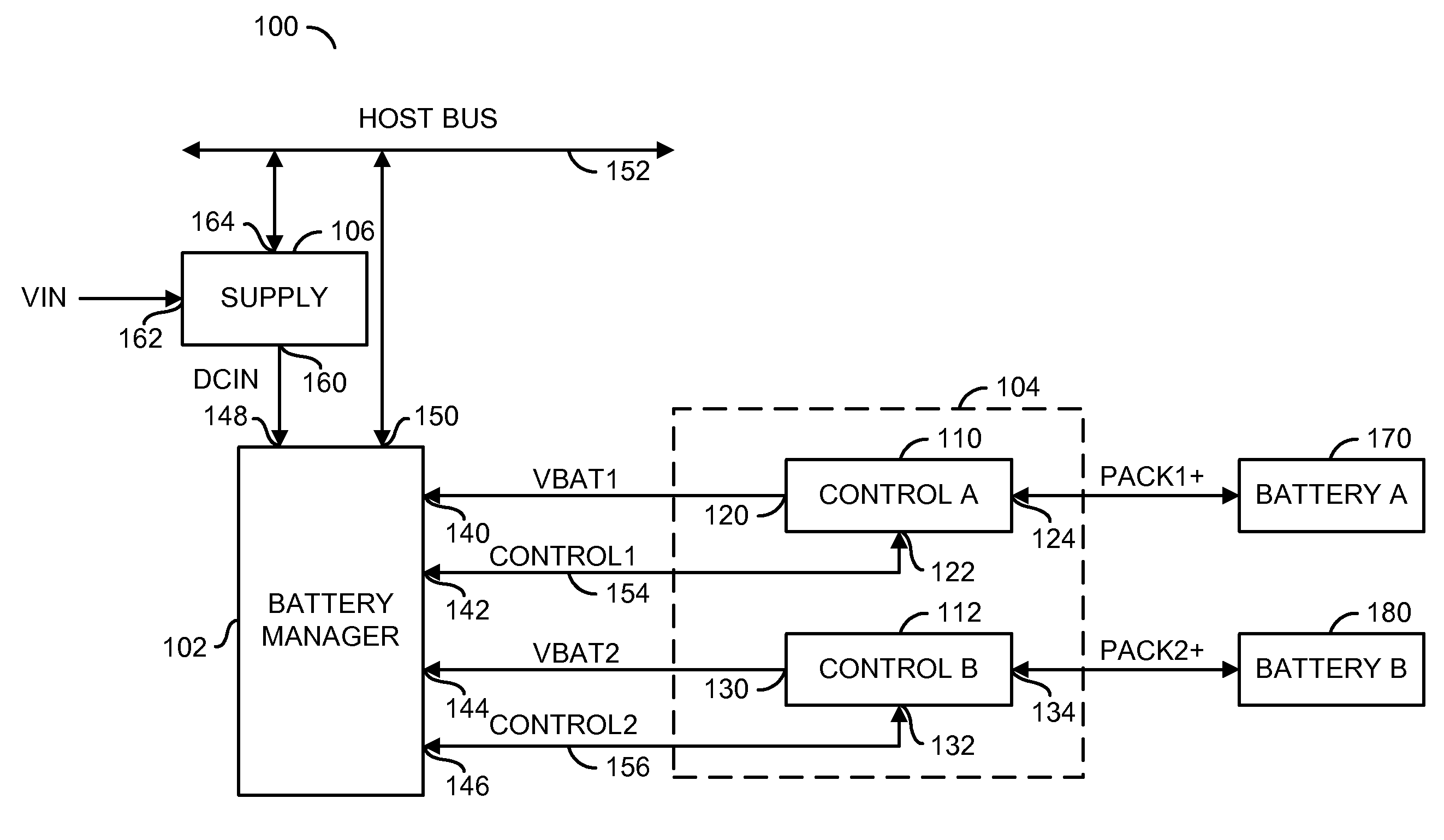
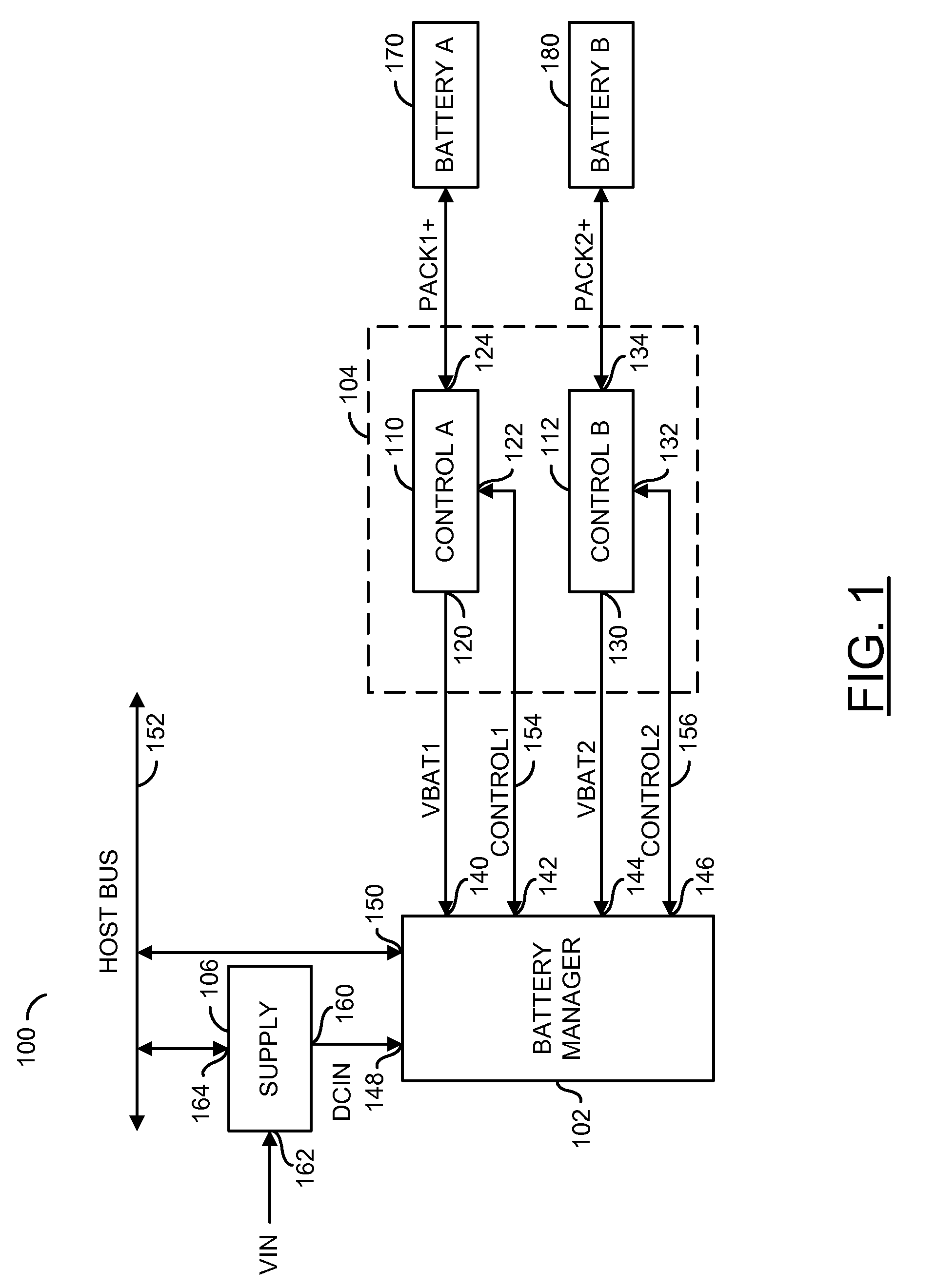
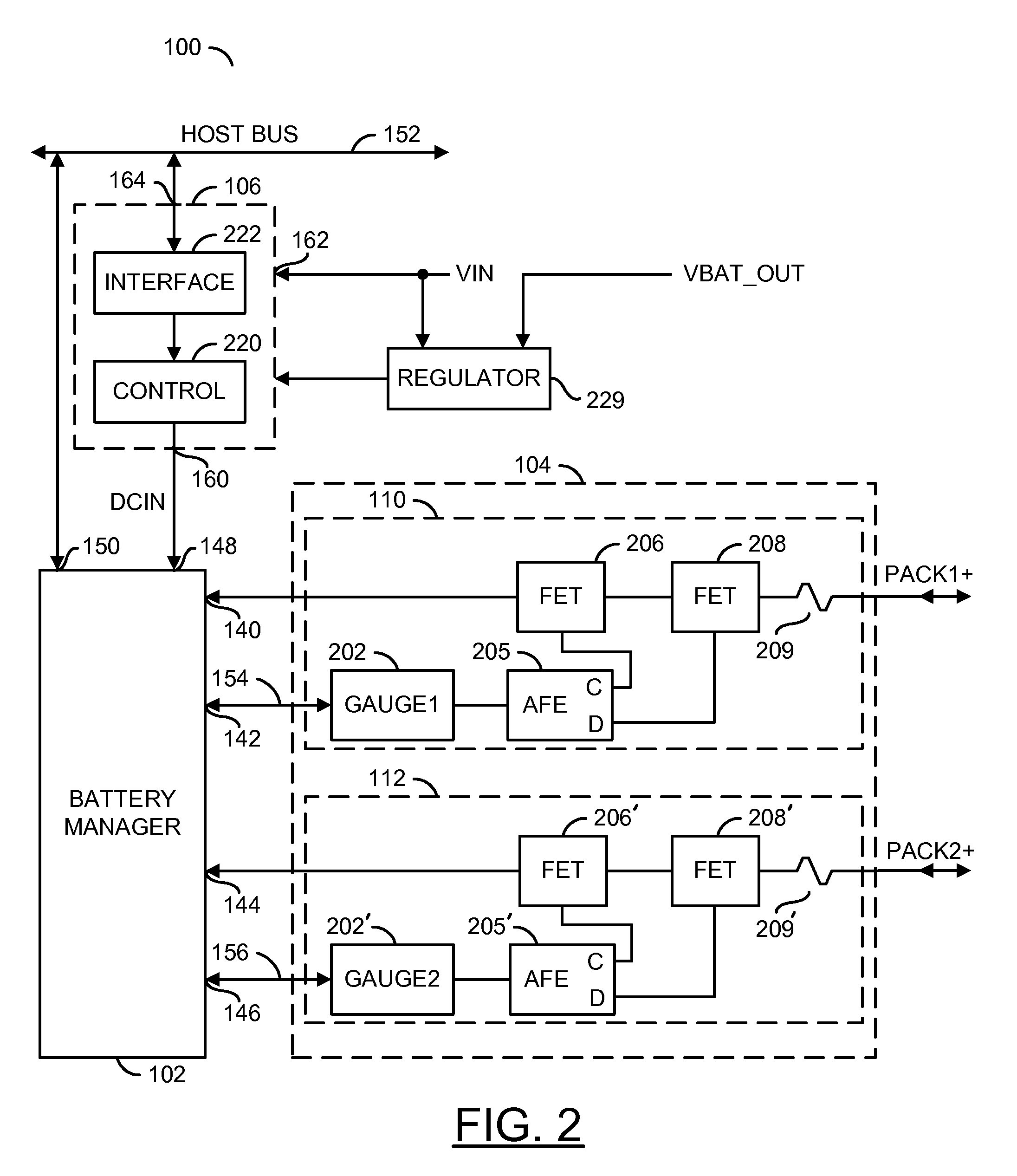
[0017]Referring to FIG. 1, a system 100 is shown in accordance with the present invention. The system 100 generally comprises a block (or circuit) 102, a block (or circuit) 104 and a block (or circuit) 106. The circuit 102 may be implemented as a battery manager circuit. The circuit 102 may include a charging portion. In one example, the circuit 102 may be implemented as an LTC1760, manufactured by Linear Technology. However, other types chargers may be implemented to meet the design criteria of a particular implementation. The LTC1760 may be an appropriate choice as the battery manager circuit 102 that provides a multiplex bus for charging, I2C communication, and / or a power path load sharing capability. The system 100 may allow the circuit 102 to operate using embedded packs that operate using multiple power supplies. The system 100 may also provide a charge / communication mode.

[0018]The circuit 104 may be implemented as a control circuit. In one example, the circuit 104 may be impl...


PUM


Abstract

The present invention concerns an apparatus comprising a charger circuit and a control circuit. The charger circuit may be configured to generate a first power down control signal and a second power down control signal in response to (i) a first charge signal, (ii) a second charge signal, (iii) a supply voltage, and (iv) a host control signal. The control circuit may be configured to generate the first charge signal and the second charge signal in response to a first battery signal and a second battery signal. The control circuit may enter a power down state in response to the host control signal initiating the power down state.

Description

[0001]This is a continuation of International Application PCT / US2008 / 008186, with an International Filing Date of Jul. 1, 2008, which claims the priority to U.S. Provisional Application No. 61 / 055,221, filed May 22, 2008, each of which is incorporated by reference in its entirety.FIELD OF THE INVENTION[0002]The present invention relates to battery backup systems generally and, more particularly, to a method and / or apparatus for implementing a battery backup system with an embedded charger that enters a sleep mode.BACKGROUND OF THE INVENTION[0003]Battery packs, such as Lithium-Ion (Li-Ion) battery packs experience a self discharge process when stored, even when not in use. Monitoring circuitry (such as an analog front end—bq29330 and / or a bq20z70, available from Texas Instruments) accelerates the discharge rate when powered by the pack cells. Preventative maintenance charging is needed to prolong battery shelf life when a monitoring gauge uses battery power to monitor a state of heal...

Claims


Application Information

Patent Timeline
Patent Type & Authority Applications(United States)
IPC IPC(8): H02J9/00H02J7/00
CPCH01M10/425H01M10/44H02J7/0057H01M2010/4271H02J7/0013H01M10/48H02J7/0069Y02E60/10
Inventor ANUPINDI, LAKSHMANA M.MARSHALL, BRAD D.SKINNER, R. BRIAN
Owner AVAGO TECH INT SALES PTE LTD
Learn More