Non-Contact Biopotential Sensor

a biopotential sensor and non-contact technology, applied in the field of low-noise, non-contact capacitive sensor systems, can solve the problems of difficult long-term recording, difficult to remove sensors upon completion of the test, and difficult to apply gel for up to an hour, so as to avoid the build-up of parasitic charge at the input node of the amplifier, the effect of avoiding the build-up of parasitic charg

Active Publication Date: 2011-02-24
RGT UNIV OF CALIFORNIA
View PDF27 Cites 35 Cited by
  • Summary
  • Abstract
  • Description
  • Claims
  • Application Information

AI Technical Summary

Benefits of technology

[0007]The present invention includes a capacitive biosensor system and method that provide a non-contact sensing plate that eliminates the need for contact with the skin surface and operates by capacitive coupling, and is capable of measuring electric fields through hair, clothing or other skin coverings. Drift and noise problems of the prior art are overcome by occasionally resetting the input node of the amplifier using a reset circuit. The timing and duration of the reset will depend on pre-determined conditions within the sensor such as direction and level of drift, or when voltage at the amplifier input exceeds a specified threshold.
[0008]In one embodiment, the inventive capacitive sensor system includes a sensing plate, an amplifier, collectively, the “basic capacitive sensor”, and a switching circuit. The sensing plate is capacitively coupled to the body surface, such as human skin, either directly or through an intervening material such as hair, clothing or other skin covering. A change in the electrical potential on the body surface generates an electric field that induces change in the electrical potential of the sensing plate. The sensing plate includes a sensing node positioned in the electric field for generating an input signal from the electric field. The sensing plate is not in contact with the body surface. The amplifier includes an input port and an output port and is configured to amplify the input signal. The amplifier receives the input signal at the input port and amplifies the input signal to generate an output signal at the output port. The output signal is communicated to a readout device such as a printer or computer monitor to generate a visual indication of the detected signals. The output signal may in addition or in lieu of immediate display be communicated to a memory device for storage and subsequent transmission, viewing and / or processing. In order to avoid the build-up of parasitic charge, a switching circuit is connected to the input port of the amplifier and a reference voltage. The switching circuit non-continuously closes a shunting path from the sensing node to the reference voltage to reset the voltage at the sensing node.
[0009]In another embodiment, the build-up of parasitic charge at the input node of the amplifier is avoided by adding a switching circuit and a unity gain amplifier to the basic capacitive sensor in the capacitive sensor circuit. The switching circuit is connected to the input port of the amplifier and a reference voltage. The switching circuit includes at least one switching device and reset circuit including a plurality of capacitors. The capacitors are configured to generate activation voltage to turn on or activate the at least one switching device. The switching circuit is connected to the input port and a reference voltage where the switching circuit is configured to non-continuously close a shunting path from the sensing node to the reference voltage to reset the sensing node when the at least one switching device is turned on. The unity gain amplifier includes a first input port and a first output port. The first input port is coupled to the input port of the amplifier and is configured to generate a first output voltage at the first output port. The unity gain amplifier is coupled to one or more resistors where the one or more resistors are configured to pull the plurality of capacitors to the first output voltage when the at least one switching device is off. Other features and advantages of the present invention will become more readily apparent to those of ordinary skill in the art after reviewing the following detailed description and accompanying drawings.

Problems solved by technology

First, it can take up to an hour to apply the gel into EEG caps that use 256 sensors.
In addition, the gel can diffuse through the hair to create shorts between sensors and can dry out over time, making long term recording very difficult.
Removal of the sensors upon completion of the test is at best unpleasant and usually fairly painful.
Generally, these approaches are limited to body areas with no hair.
A disadvantage is that the bristle pads can be relatively expensive to manufacture.
A drawback of such capacitively coupled electrical sensors is that parasitic charge builds up due to sensor drift and input bias offset currents.
The problem with such a scheme is that the high-valued resistor that is used contributes excessive amounts of thermal noise, contaminating the signal.
However, such circuits can also introduce noise and have relatively high power requirements.

Method used


Image

  • Non-Contact Biopotential Sensor
  • Non-Contact Biopotential Sensor
  • Non-Contact Biopotential Sensor

Examples


Embodiment Construction

[0019]A device for recording of electrical potentials on the surface of the human body is described. The following description sets forth numerous specific details such as examples of specific systems, components, methods, and so forth, in order to provide a good understanding of several embodiments of the present invention. It will be apparent to one skilled in the art, however, that at least some embodiments of the present invention may be practiced without these specific details. In other instances, well-known components or methods are not described in detail or are presented in simple block diagram format in order to avoid unnecessarily obscuring the present invention. Thus, the specific details set forth are merely exemplary. Particular implementations may vary from these exemplary details and still be contemplated to be within the spirit and scope of the present invention.

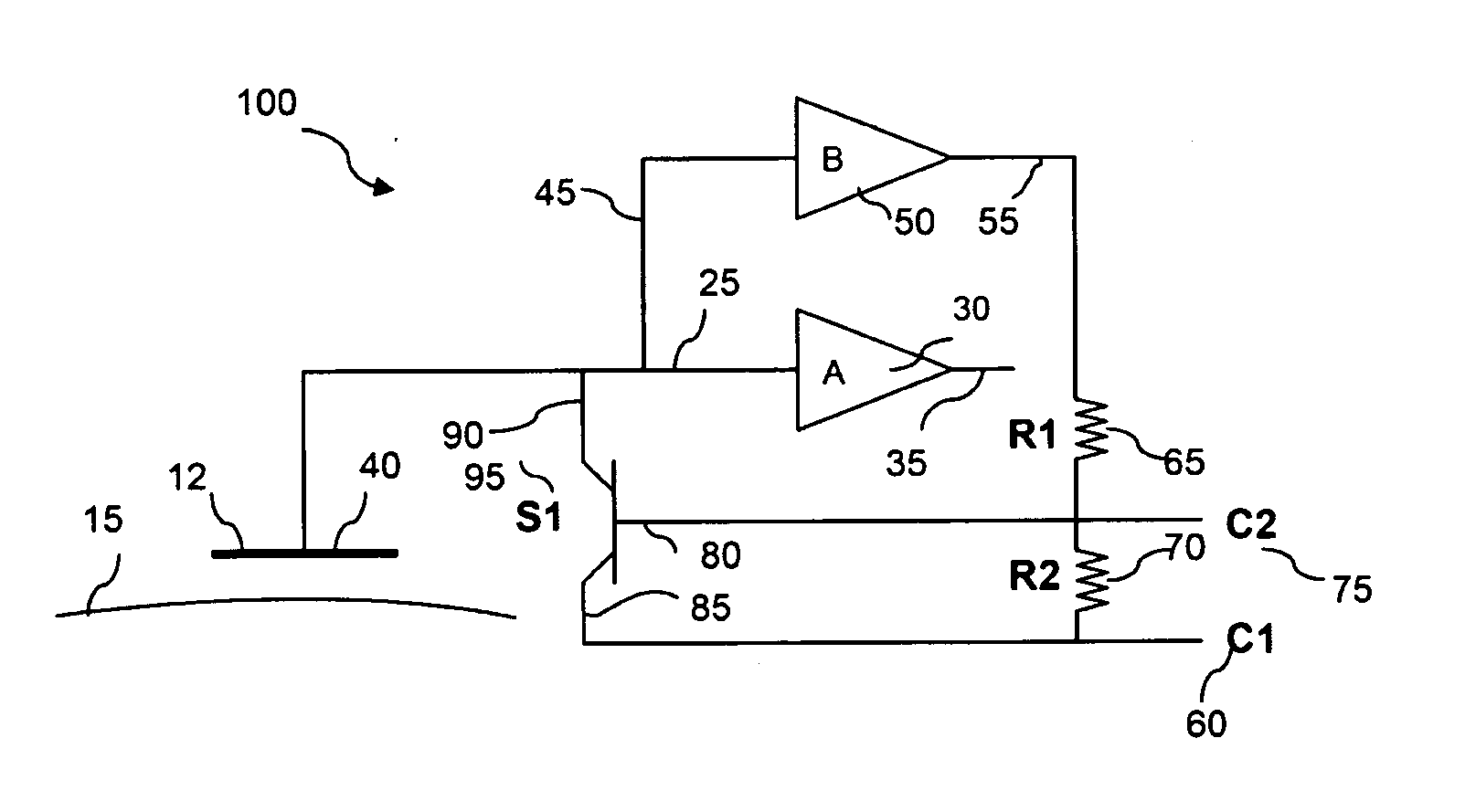
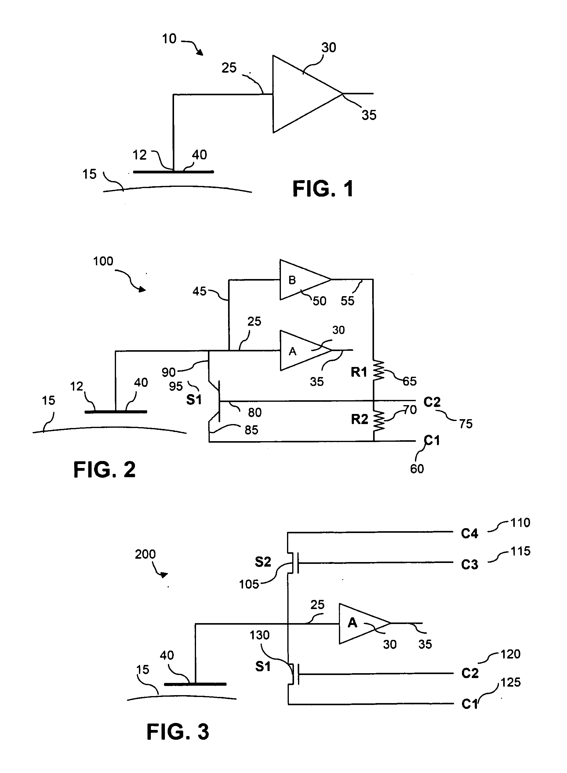
[0020]FIG. 1 illustrates one embodiment of capacitive sensor system for recording of electrical potentials...


PUM


Abstract

A capacitive sensor system including a sensing plate, an amplifier, and a switching circuit is described. The sensing plate is capacitively coupled to a body surface. A change in the electric potential on the body surface generates an electric field that induces change in the electric potential of the sensing plate. The sensing plate includes a sensing node positioned in the electric field for generating an input signal from the electric field. The sensing plate is not in contact with the body surface. The amplifier receives the input signal at the input port, amplifies the input signal and generates an output signal at the output port. The switching circuit is connected to the input port and a reference voltage. The switching circuit non-continuously closes a shunting path from the sensing node to the reference voltage to reset the voltage at the sensing node.

Description

RELATED APPLICATIONS[0001]This application claims the benefit of U.S. Provisional Patent Application Ser. No. 60 / 990,629, filed Nov. 28, 2007, entitled “NON-CONTACT BIOPOTENTIAL SENSOR,” which is hereby incorporated by reference in its entirety.FIELD OF THE INVENTION[0002]This invention relates to a low-noise, non-contact capacitive sensor system to measure electrical voltage signals generated by the body without direct contact with the body surface.BACKGROUND[0003]Electroencephalogram (EEG) and electrocardiogram (ECG or EKG) sensors measure the time-varying magnitude of electric fields emanating from the brain and heart, respectively, as a result of cellular activity within the organ. Currently available sensors for measurement of these electrical potentials require direct electrical contact with the skin, which can be achieved by using conductive gel between the sensor and the skin or by abrading the skin. While the gel satisfies the aim of making a good contact, there are several...

Claims


Application Information

Patent Timeline
Patent Type & Authority Applications(United States)
IPC IPC(8): G01R27/26A61B5/308
CPCA61B5/04004A61B5/0478A61B5/04284A61B5/7225A61B5/30A61B5/302A61B5/291
Inventor SULLIVAN, THOMAS J.CAUWENBERGHS, GERTDEISS, STEPHEN R.
Owner RGT UNIV OF CALIFORNIA
Why Eureka
Try Eureka