Conversion circuit, display drive circuit, electro-optical device and electronic equipment

a display drive and conversion circuit technology, applied in the field of conversion circuits, display drive circuits, electrooptical devices and electronic equipment, can solve the problems of increasing the circuit scale, the data amount of image data to be handled becomes substantially large, and the image data needs to be processed at high speed, so as to increase the circuit scale and increase the operation speed

Inactive Publication Date: 2011-02-24
SEIKO EPSON CORP
View PDF6 Cites 9 Cited by
  • Summary
  • Abstract
  • Description
  • Claims
  • Application Information

AI Technical Summary

Benefits of technology

[0009]In accordance with an advantage of some aspects of the invention, it is possible to provide conversion circuits, display drive circuits and electro-optical devices which are capable of realizing high-definition display without causing a substantial increase in the circuit scale or an increase in the operation speed, and electronic equipment equipped with the electro-optical device.

Problems solved by technology

As the number of gradations increases as the resolution becomes higher, the data amount of image data to be handled becomes substantially large, such that the image data needs to be processed at high speed.
To process such a huge amount of image data at high speed, it is necessary not only to prepare high-speed circuit elements to process the image data but also to newly prepare a high speed data bus, which can lead to a problem of an increased circuit scale.
This would make the operation speed extremely high, which could reach several GHz, and lead to problems, such as, increased difficulty in designing, higher power consumption, and the like.

Method used


Image

  • Conversion circuit, display drive circuit, electro-optical device and electronic equipment
  • Conversion circuit, display drive circuit, electro-optical device and electronic equipment
  • Conversion circuit, display drive circuit, electro-optical device and electronic equipment

Examples


Embodiment Construction

[0041]A conversion circuit, a display drive circuit, an electro-optical device and an electronic apparatus in accordance with embodiments of the invention are described in detail below with reference to the accompanying drawings. It is noted that the embodiments to be described below are only some parts of modes of the invention, and do not limit the invention, and can be arbitrarily changed within the range of the technological concept of the invention.

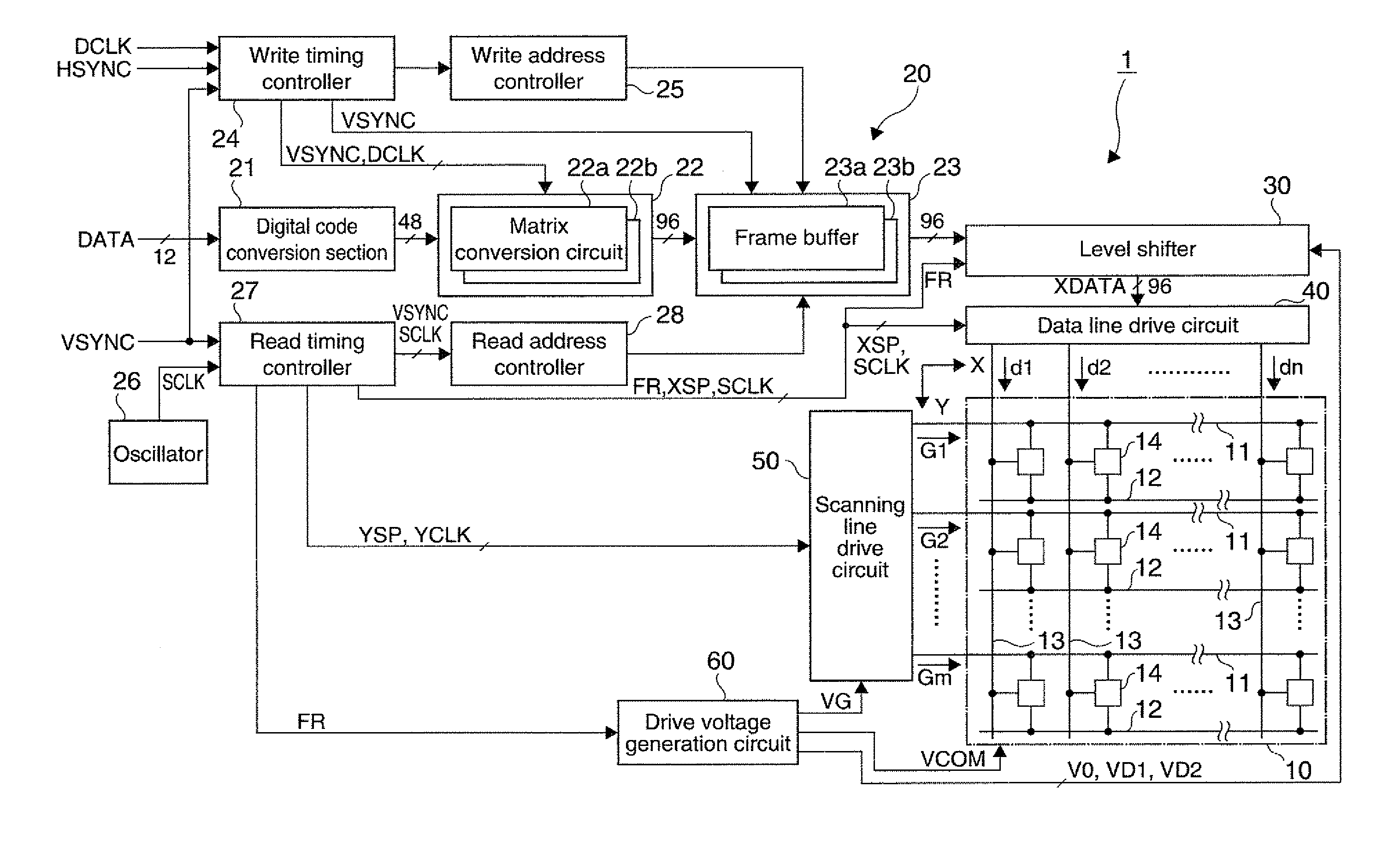
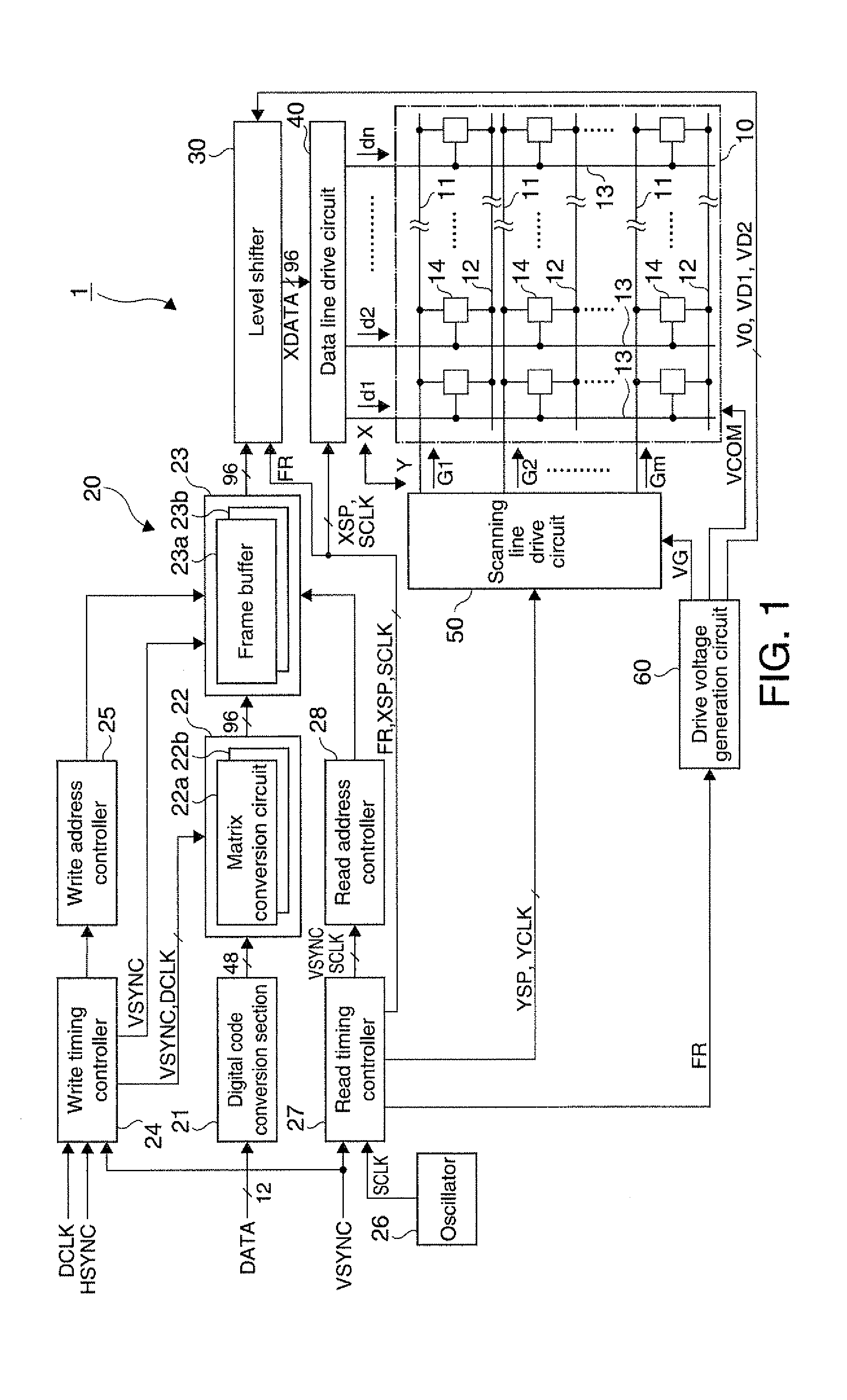
[0042]FIG. 1 is a block diagram showing a composition of a main portion of an electro-optical device in accordance with an embodiment of the invention. The electro-optical device will be described, using a liquid crystal device as an example. As shown in FIG. 1, a liquid crystal device 1 is equipped with a liquid crystal panel 10, a display drive circuit 20, a level shifter 30, a data line drive circuit 40, a scanning line drive circuit 50, and a drive voltage generation circuit 60, wherein the drive circuit such as the display drive...


PUM


Abstract

A display drive circuit that performs digital driving for displaying an image of each one frame based on luminance data of a plurality of subframes is disclosed. The display drive circuit includes a conversion section that converts the luminance data having a plurality of bits indicating a luminance level of each of the plurality of subframes into data indicating the luminance level for pixels in a number greater than the number of the plurality of subframes, and a storage section that stores the data converted by the conversion section.

Description

[0001]The present application claims a priority based on Japanese Patent Application No. 2009-193524 filed on Aug. 24, 2009, the contents of which are incorporated herein by reference.BACKGROUND[0002]1. Technical Field[0003]The present invention relates to a conversion circuit that converts data to be used for image display, a display drive circuit equipped with the conversion circuit, an electro-optical device equipped with the display drive circuit, and electronic equipment equipped with the electro-optical device.[0004]2. Related Art[0005]It is commonly known that an electro-optical device is equipped with a plurality of scanning electrodes (scanning lines), a plurality of signal electrodes (data lines) and a plurality of pixels provided at position where these scanning electrodes and the signal electrodes intersect one another, wherein a gradation signal (image data) corresponding to the gradation of each pixel is supplied to each of the pixels corresponding to selected ones of ...

Claims


Application Information

Patent Timeline
Patent Type & Authority Applications(United States)
IPC IPC(8): G09G5/10
CPCG09G3/2022G09G3/3648G09G3/3614G09G3/3611
Inventor MATSUMOTO, TETSURO
Owner SEIKO EPSON CORP
Why Eureka
Try Eureka