
Optimized layer-2 network switching systems and methods

a network switching and layer-2 technology, applied in data switching networks, frequency-division multiplexes, instruments, etc., can solve problems such as devices and protocols tend to cause congestion in optical transport networks, and may be especially problemati

Active Publication Date: 2011-02-24
VERIZON PATENT & LICENSING INC
View PDF13 Cites 29 Cited by
  • Summary
  • Abstract
  • Description
  • Claims
  • Application Information

AI Technical Summary

Benefits of technology

The patent describes a system and method for optimizing data traffic forwarding in communication networks, particularly in optical transport networks. The system monitors the performance of multiple network paths and selects the best path for forwarding data traffic based on a path selection heuristic and the monitored performance of the paths. This approach helps to prevent congestion and improve network efficiency. The technical effect of the patent is to provide an improved solution for forwarding data traffic in communication networks, particularly in large-scale and hybrid configurations, to prevent congestion and improve network performance.

Problems solved by technology

While the simple data traffic forwarding functionality of a data link layer device such as a conventional Ethernet switch device is well-suited for certain types of communication networks such as a small-scale local area network, it is problematic for other types of communication networks.
For example, traditional Ethernet switch devices and protocols tend to cause congestion in optical transport networks and particularly in hybrid data link layer and optical transport network configurations.
The congestion may be especially problematic when such hybrid configurations are used to transport significant loads of data traffic over large-capacity physical links and / or large geographic areas such as may be used in a backhaul network and / or a wide area network (e.g., a metro area network).
While the network layer is typically configured to perform path detection, data traffic routing, error control, quality-of-service (“QOS”), and other “intelligence-type” functions, such functions at the network layer do not always prevent congestion of physical links interconnecting network devices.
Moreover, overhead associated with the network layer is significantly more than overhead associated with the data link layer.

Method used


Image

  • Optimized layer-2 network switching systems and methods
  • Optimized layer-2 network switching systems and methods
  • Optimized layer-2 network switching systems and methods

Examples


Embodiment Construction

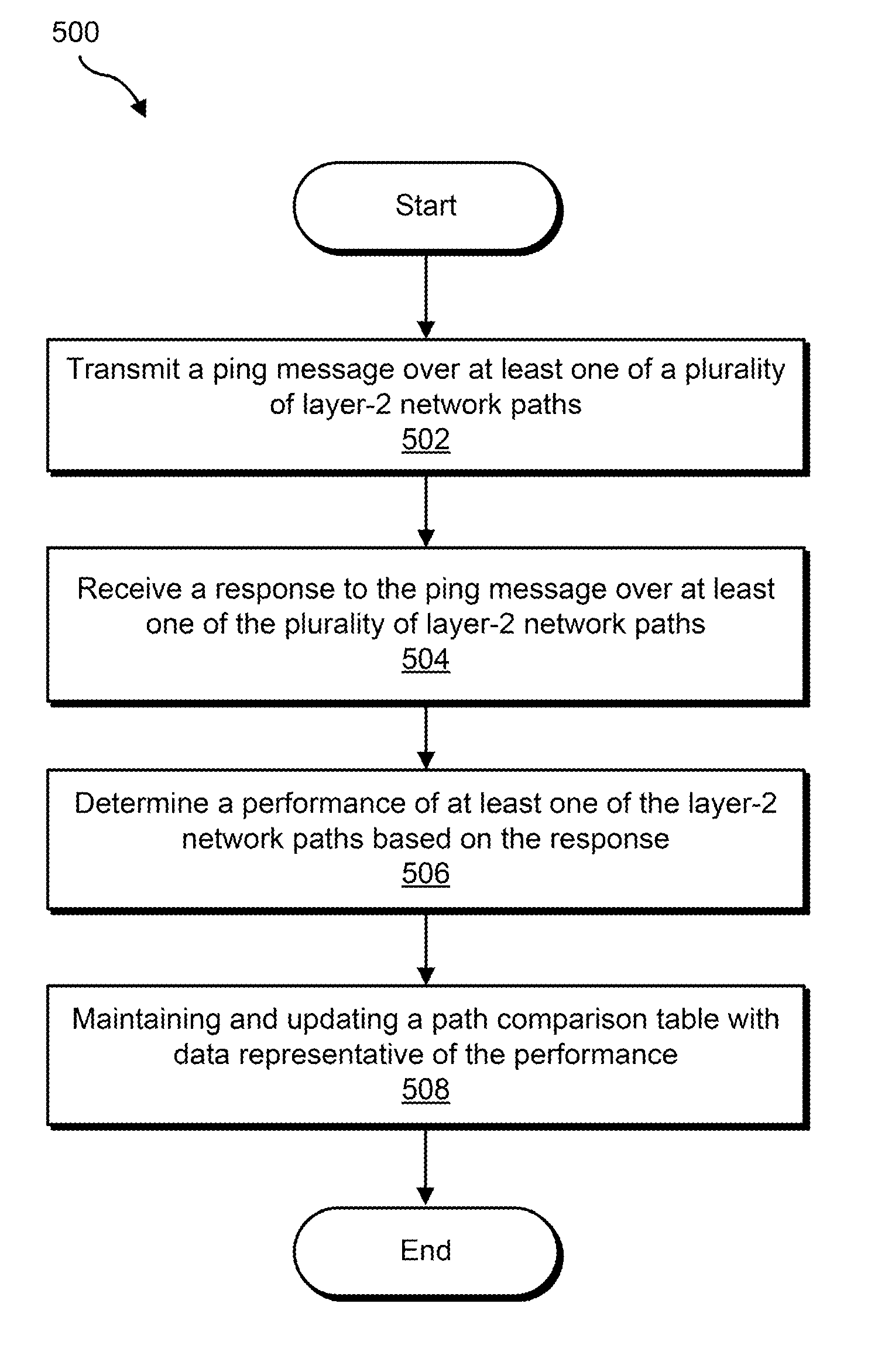
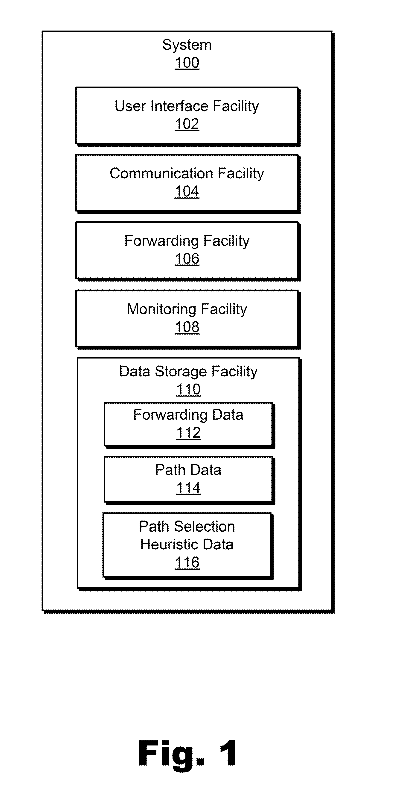
[0015]Exemplary optimized layer-2 network switching systems and methods are described herein. As described herein, exemplary systems and methods may monitor a performance of at least one of a plurality of layer-2 network paths and select an optimal one of the plurality of layer-2 network paths over which to forward layer-2 data traffic based on a path selection heuristic and the monitored performance of the at least one of the plurality of layer-2 network paths. Data traffic may then be forwarded over the selected optimal layer-2 network path.

[0016]For example, an exemplary method includes monitoring a performance of at least one of a plurality of layer-2 network paths connecting a layer-2 network switch device to another layer-2 network switch device and selecting an optimal one of the plurality of layer-2 network paths over which to forward data traffic based on a path selection heuristic and the monitored performance of the at least one of the plurality of layer-2 network paths. ...


PUM


Abstract

An exemplary method includes monitoring a performance of at least one of a plurality of layer-2 network paths connecting a layer-2 network switch device to another layer-2 network switch device and selecting an optimal one of the plurality of layer-2 network paths over which to forward data traffic based on a path selection heuristic and the monitored performance of the at least one of the plurality of layer-2 network paths. At least a portion of the exemplary method may be performed by a layer-2 network switching system. In certain embodiments, the selecting of the optimal one of the plurality of layer-2 network paths over which to forward the data traffic is based on at least one of a latency parameter, a congestion parameter, and a cost parameter associated with the at least one of the plurality of layer-2 network paths. Corresponding systems and methods are also disclosed.

Description

BACKGROUND INFORMATION[0001]Communication networks provide many people and organizations with access to a variety of applications and services. A typical communication network employs a layered communication and protocol design in which each layer represents a collection of conceptually similar functions. The layers are arranged hierarchically, with each layer typically providing services to the layer above it and requesting services from the layer below it.[0002]As an example, a typical layered design of a communication network patterned after the Open Systems Interconnection (“OSI”) reference model includes a physical layer, data link layer, network layer, transport layer, session layer, presentation layer, and application layer arranged hierarchically. The physical layer, data link layer, and network layer are commonly referred to as “media layers,” and the other four layers are commonly referred to as “host layers.”[0003]The physical layer includes functions concerned with inter...

Claims


Application Information

Patent Timeline
Patent Type & Authority Applications(United States)
IPC IPC(8): H04L12/26H04L1/00H04L12/28H04L45/02H04L45/121H04L45/24
CPCH04L12/462H04L43/10H04L45/00H04L45/26H04L45/121H04L45/22H04L45/02
Inventor KAKADIA, DEEPAKPARKER, BENJAMIN J.TAN, THOMAS H.
Owner VERIZON PATENT & LICENSING INC
Learn More