Optical communications system

Active Publication Date: 2011-02-24
SUMITOMO ELECTRIC IND LTD
View PDF7 Cites 7 Cited by
  • Summary
  • Abstract
  • Description
  • Claims
  • Application Information

AI Technical Summary

Benefits of technology

[0012]The present invention has been developed to eliminate the problems described above. It is an object of the present invention to provide an o

Problems solved by technology

While doing so contributes to improving OSNR, it also entails the power increasin

Method used


Image

  • Optical communications system
  • Optical communications system
  • Optical communications system

Examples


Embodiment Construction

[0023]In the following, embodiments of an optical communications system according to the present invention will be explained in detail with reference to FIGS. 1 to 3, 4A to 5B and 6. In the description of the drawings, identical or corresponding components are designated by the same reference numerals, and overlapping description is omitted.

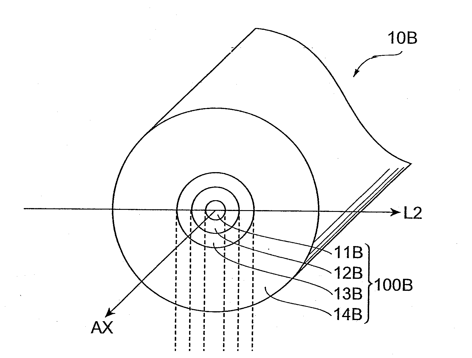
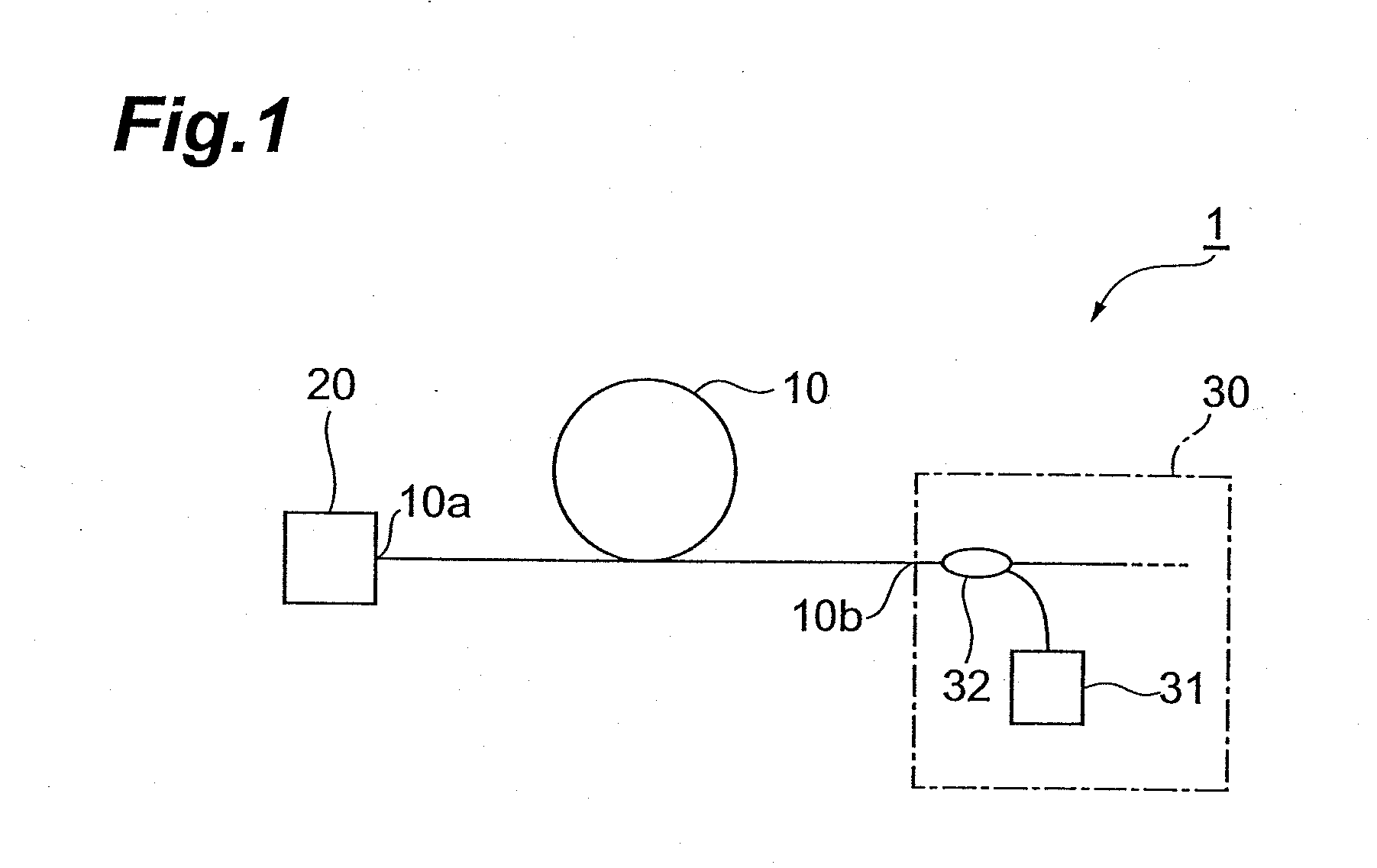
[0024]FIG. 1 is a view showing the configuration of an optical communications system 1 according to the present embodiment. The optical communications system 1 according to the present embodiment comprises a transmitter station, one or more repeater stations, a receiver station, and an optical fiber 10 serving as a transmission medium, namely an optical fiber laid in the transmission section that is positioned between the transmitter station (or repeater station) and the receiver station (or repeater station). Particularly, as shown in FIG. 1, one end 10a of the optical fiber 10 is optically connected to the transmitter station (or repeater stati...


PUM


Abstract

The present invention relates to an optical communications system that allows improving OSNR while suppressing the power increase of pumping light for distributed Raman amplification. In the optical communications system, an optical fiber is laid in a transmission section between a transmitter station (or repeater station) and a receiver station (or repeater station), and optical signals are transmitted from the transmitter station to the receiver station via the optical fiber. In the optical communications system, pumping light for Raman amplification, outputted by a pumping light source provided in the receiver station, is fed into the optical fiber via an optical coupler, and the optical signals are distributed-Raman-amplified in the optical fiber. The transmission loss and the effective area of the optical fiber satisfy, at the wavelength of 1550 nm, a predetermined relationship.

Description

BACKGROUND OF THE INVENTION[0001]1. Field of the Invention[0002]The present invention relates to an optical communications system in which optical signals are transmitted via an optical fiber laid in a transmission section.[0003]2. Related Background of the Invention[0004]In order to reduce the number of repeater stations by elongating each transmission section and to transmit large volumes of information, optical SN ratio (OSNR) is preferably large, in optical communications systems in which optical signals are transmitted via an optical fiber laid in a transmission section. In order to increase OSNR, transmission loss in the optical fiber are preferably small, and the effective area of the optical fiber is preferably large.[0005]Jianjun Yu, et al., ECOC 2008, Th3.E2 (Document 1) disclose results of a transmission experiment that achieved a total transmission capacity of 17 Tbps with 114 Gbps×161 wavelengths by 8PSK modulation, using an optical fiber SMF-28ULL (by Corning) 662 km l...

Claims


Application Information

Patent Timeline
IPC IPC(8): H04B10/12G02F1/35H04B10/25H04B10/2507H04B10/291
CPCG02B6/02019H04B10/2916G02B6/0365
Inventor SASAOKA, EISUKEKUWAHARA, KAZUYA
Owner SUMITOMO ELECTRIC IND LTD
Why Eureka
Try Eureka