

Hydrophobicizing apparatus, hydrophobicizing method and storage medium
- Summary
- Abstract
- Description
- Claims
- Application Information
AI Technical Summary
Benefits of technology
Problems solved by technology
Method used
Image

Examples
Embodiment Construction
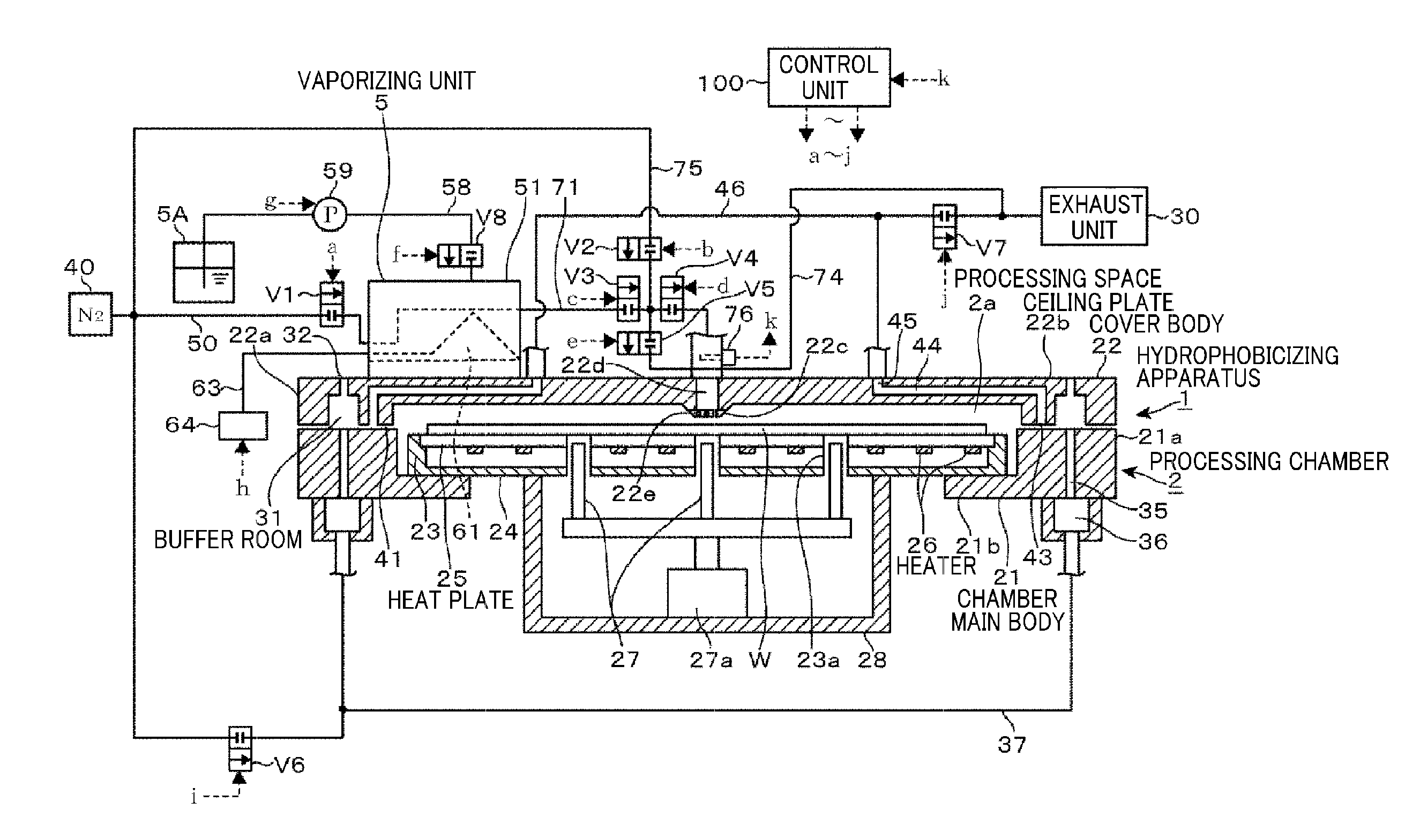
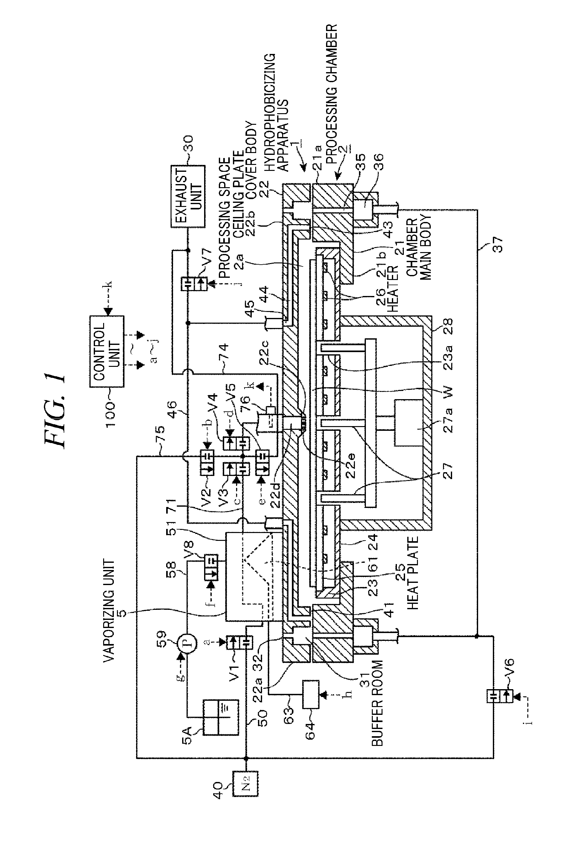
[0030]Hereinafter, embodiments of a hydrophobicizing apparatus in accordance with the present disclosure will be described with reference to the accompanying drawings. A hydrophobicizing apparatus 1 includes, as illustrated in FIG. 1, a processing chamber 2 configured to perform a hydrophobicizing process on a substrate such as a wafer W; and a vaporizing unit (vaporizing device) 5 configured to generate a HMDS gas (hydrophobicizing gas) to be introduced into processing chamber 2. The hydrophobicizing apparatus 1 is hermetically accommodated in a non-illustrated housing.
[0031]The processing chamber 2 includes a chamber main body 21 having an open top; and a cover body 22 installed to close the open top. The chamber main body 21 includes a sidewall 21a and a bottom 21b. A mounting table 23 for a wafer W is supported by the bottom 21b of the chamber main body 21. In the processing chamber 2 in accordance with the present embodiment, the bottom 21b is extended to a region supporting a ...
PUM
| Property | Measurement | Unit |
|---|---|---|
| Temperature | aaaaa | aaaaa |
| Concentration | aaaaa | aaaaa |
Abstract
Description
Claims
Application Information