

Integrated separation and detection cartridge with means and method for increasing signal to noise ratio
a detection cartridge and integrated technology, applied in the separation of components, biochemistry apparatus, biochemistry apparatus and processes, etc., can solve the problems of interference with reliable and reproducible signal (analyte detection), and achieve the effect of low background noise, efficient washing procedures, and efficient mixing procedures
- Summary
- Abstract
- Description
- Claims
- Application Information
AI Technical Summary
Benefits of technology
Problems solved by technology
Method used
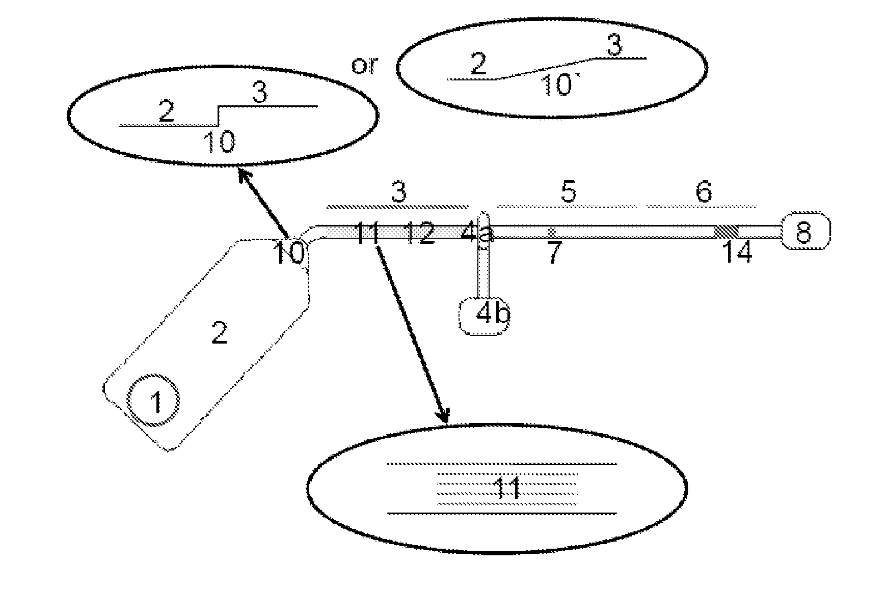
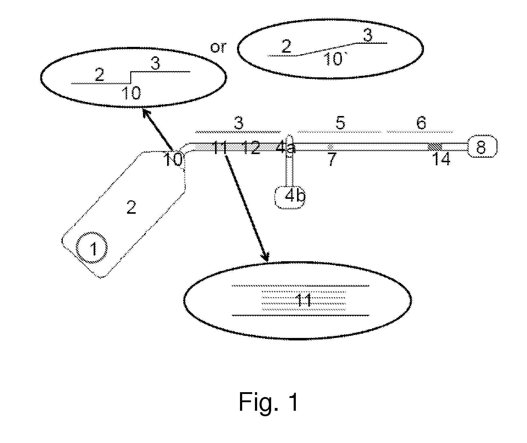
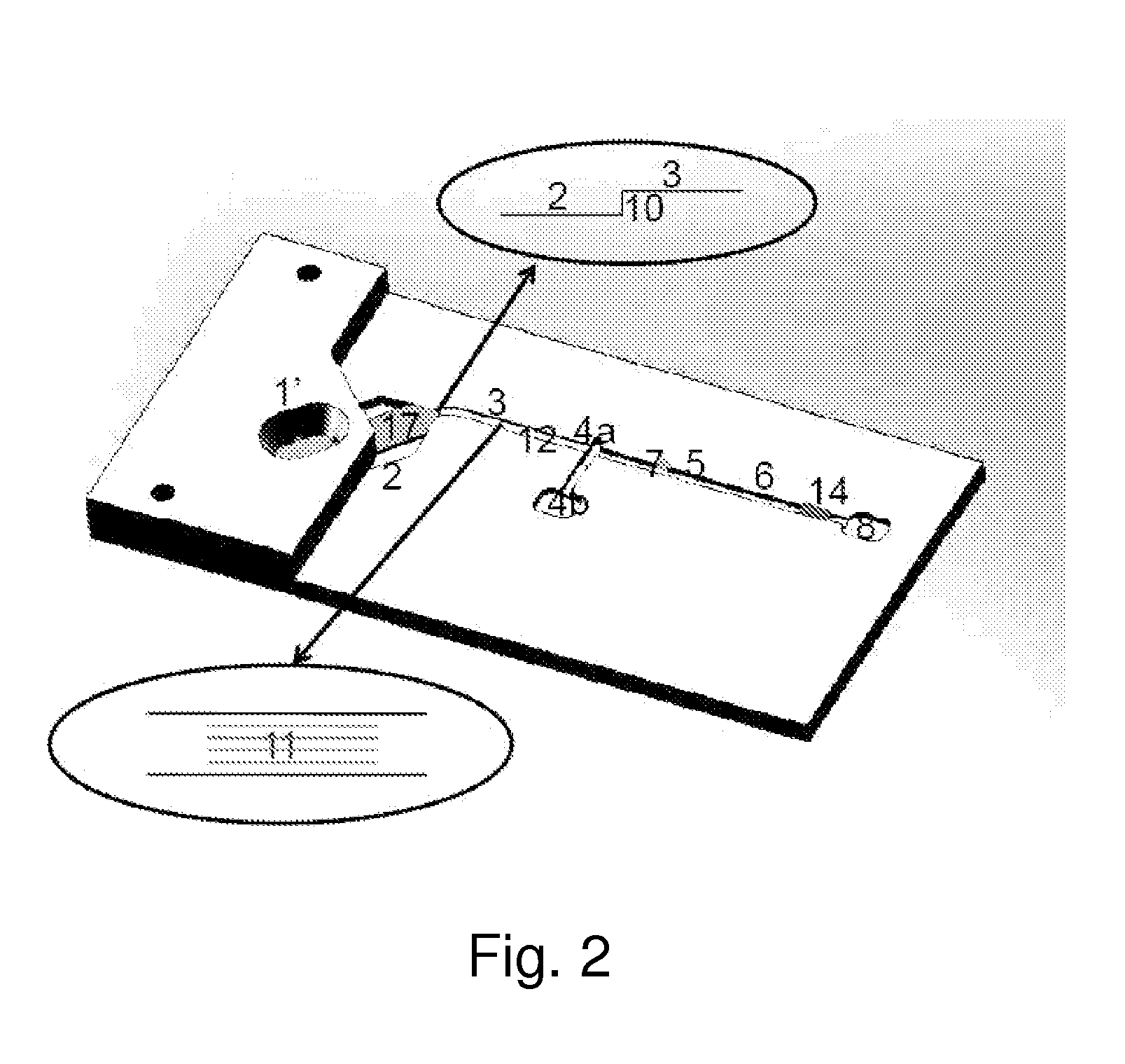
Image

Examples
example 1
[0113]An Assay Cycle in the Integrated Separation and Detection Device
[0114]The purpose of this example was to illustrate[0115]1. The measuring principle with the analyte Brain Natriuretic Peptide (BNP) as example[0116]2. The detection limit[0117]3. The detection range[0118]4. The CV values at different BNP concentrations[0119]5. Measuring of BNP in blood samples
[0120]Materials
[0121]Standards: Range 0 pg / ml-16,000 pg / ml BNP was measured by use of the method in this example.
[0122]Samples: 4 different blood samples from healthy volunteers and 4 different samples from patients with heart failure were measured by use of the method in this example.
[0123]Antibodies: Magnetic particles (MP) coated with BNP monoclonal catching antibody. Tracer antibody is a HRP label monoclonal BNP antibody. Tracer antibody was placed directly in the blood separation filter.
[0124]Blood stabilizing reagent: EDTA is added to either the capillary channel or the blood sample.
[0125]Washing solution: TBS+0.05wt. ...
PUM
| Property | Measurement | Unit |
|---|---|---|
| volume | aaaaa | aaaaa |
| angle | aaaaa | aaaaa |
| angle | aaaaa | aaaaa |
Abstract
Description
Claims
Application Information