System and method for changing the state of vehicle components

a technology for electronic/electric vehicles and components, applied in data switching networks, instruments, high-level techniques, etc., can solve the problems of hardware dependence and strong relationship to existing infrastructure, and the method and system cannot be used for vehicles having a simple bus or network structure, and achieve the effect of facilitating transfer requests

Inactive Publication Date: 2011-02-24
VOLVO LASTVAGNAR AB
View PDF9 Cites 42 Cited by
  • Summary
  • Abstract
  • Description
  • Claims
  • Application Information

AI Technical Summary

Benefits of technology

[0032]In a further preferred embodiment, each state change component can propagate transfer requests received on one network segment or via a dedicated activation lines to other network segments or activation lines attached to the ECU. For that, the dedicated activation lines are adapted to uniquely identify the concerned infrastructural subset. In this way, it is possible to propagate transfer requests from one network segment to any other network segment via one or more (gateway) state change components.

Problems solved by technology

Disadvantageous, the disclosed method and system can only be used for vehicles having a simple bus or network structure, particularly having only a single bus connecting all ECUs in the vehicle.
A possibility to activate more than one network segment with a single request is not possible.
Further, the disclosed power management module only controls the power state of an ECU, wherein the power states of loads and other control units connected and controlled by the same control unit cannot be controlled.
Another disadvantage of the existing solutions is that they are hardware dependent and strongly related to the existing infrastructure.

Method used


Image

  • System and method for changing the state of vehicle components
  • System and method for changing the state of vehicle components
  • System and method for changing the state of vehicle components

Examples


Embodiment Construction

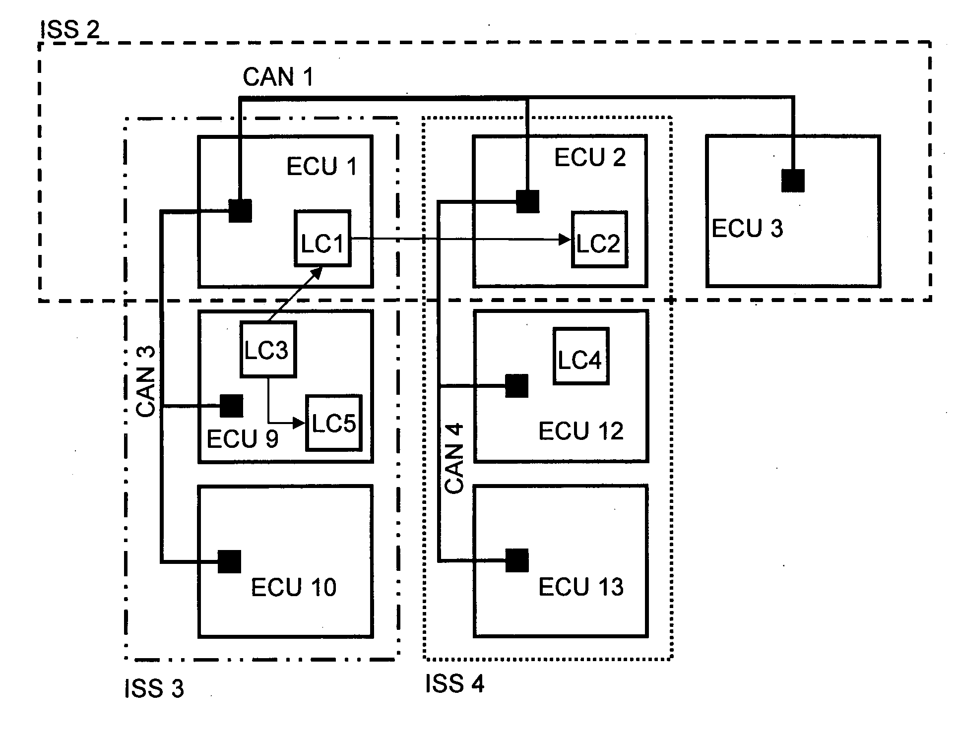
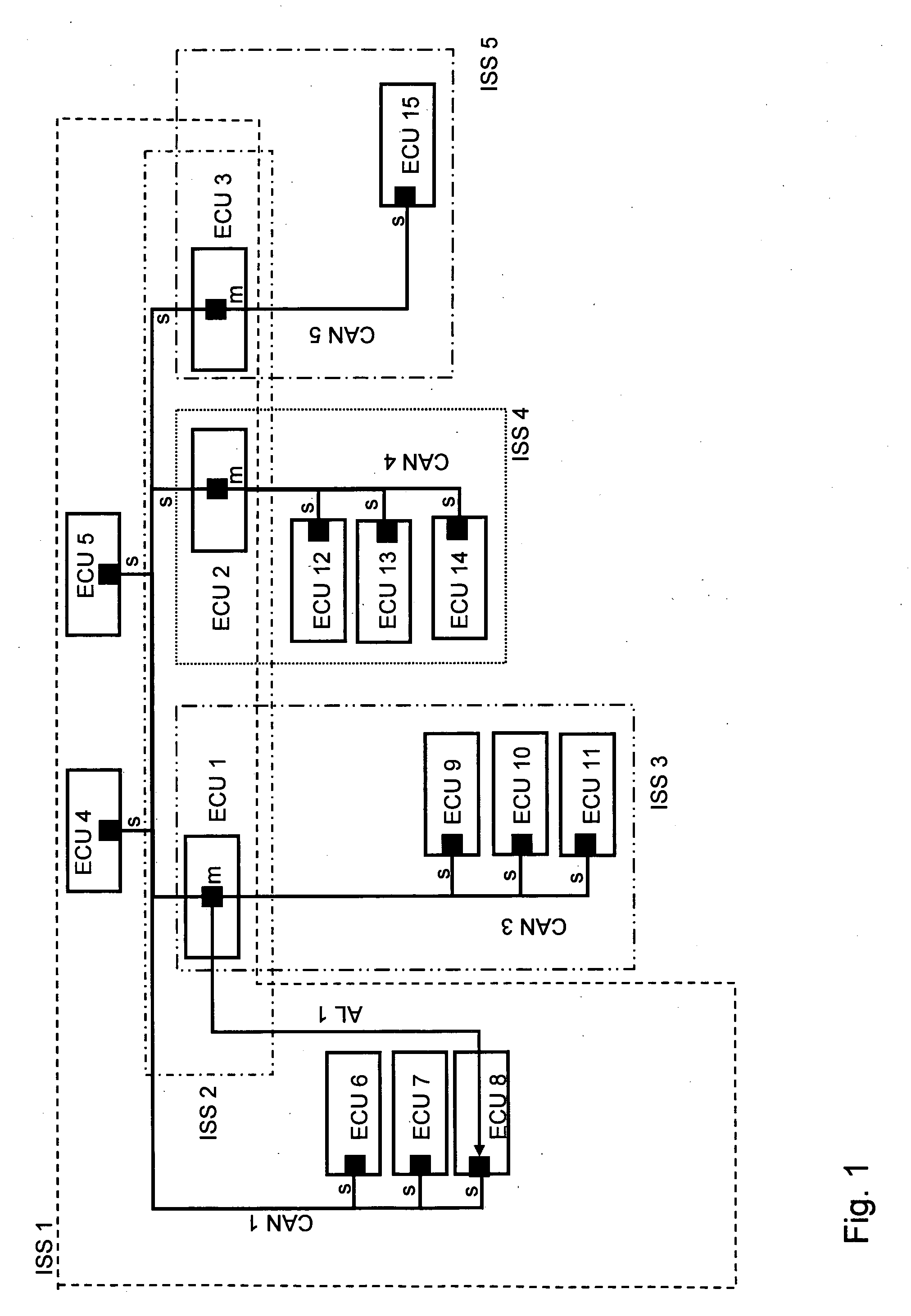
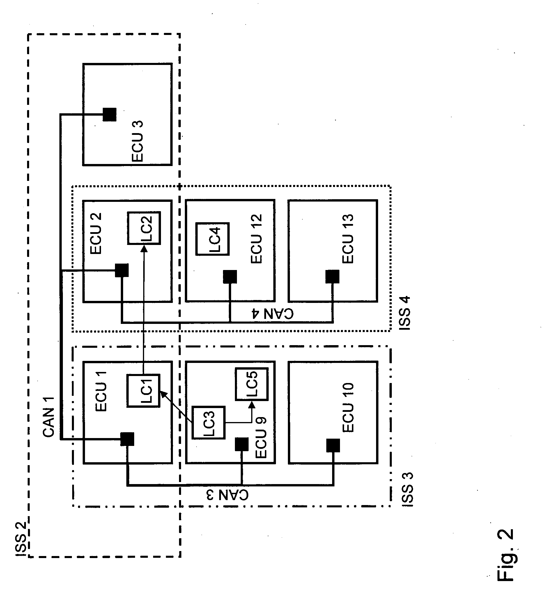
[0039]FIG. 1 shows a preferred embodiment of an electronic / electric vehicle infrastructure system according to the invention comprising a plurality of infrastructure subsystems ISS1 which are indicated by ISS1, ISS2, ISS3, ISS4 and ISS5. The shown five infrastructure subsets are exemplary only, since a vehicle infrastructure system can comprise easily more than 30 infrastructure subsystems. Each infrastructure subsets can comprise an arbitrary number of electronic control units (ECU1-ECU15), loads connected to the ECU (not shown), and / or network segments (CAN1-CAN5), particularly bus systems. In the shown embodiment a network segment is a CAN bus connecting ECUs. It should also be noted that ECUs and network segments can be part of more than one infrastructure subsystem, i.e. different infrastructure subsystems can overlap.

[0040]The vehicle's electronic / electric infrastructure provides the electric and / or electronic functions or functionalities of the vehicle which in turn can be pr...


PUM


Abstract

An electronic/electric vehicle infrastructure system is provided for controlling the electronic/electric functions and/or functionalities of a vehicle as well as a method for controlling such a system, wherein the electronic/electric vehicle infrastructure system includes at least two electronic/electric vehicle infrastructure subsets each including a plurality of electronic/electric vehicle infrastructure elements, wherein an electronic/electric infrastructure element is an electronic control unit (ECU), a network segment and/or a load, and at least one electronic/electric vehicle infrastructure element is transferable in an active or inactive state, and wherein the electronic/electric functions and/or functionalities are defined by predetermined vehicle modes and/or predetermined applications needing predetermined ECUs and/or loads, wherein each ECU includes a state change component for transferring the ECU, at least one connected load and/or at least one network segment attached to the ECU into an active or inactive state, wherein each state change component is adapted to receive, transfer and/or execute a state transfer request initiated by a change of the current predetermined vehicle mode and/or by application needs.

Description

BACKGROUND AND SUMMARY[0001]The present invention relates to an electronic / electric vehicle infrastructure system for controlling the electronic / electric functions and / or functionalities of a vehicle and a method for controlling such a system, wherein the electronic / electric vehicle infrastructure system comprises at least one electronic / electric vehicle infrastructure subsets each comprising a plurality of electronic / electric vehicle infrastructure elements, wherein an electronic / electric infrastructure element is an electronic control unit (ECU), a network segment and / or a load, and at least one electronic / electric vehicle infrastructure element is transferable in an active or inactive state, and wherein the activity of the electronic / electric functions and / or functionalities are defined by predetermined vehicle modes and / or predetermined application-specific contexts.[0002]In order to reduce the power consumption in the vehicle, there is a need to develop infrastructure solutions...

Claims


Application Information

Patent Timeline
Patent Type & Authority Applications(United States)
IPC IPC(8): G06F19/00
CPCH04L12/12H04L12/40039H04L12/462Y02B60/34H04L2012/40273Y02B60/32H04L2012/40215Y02D30/50
Inventor HONNER, MATSISAKSSON, PATRIKOHLSSON, JOAKIMJARENMARK, ROLFSODERBERG, JANWESTERLIND, HANSRONNLUND, JANRIBERO, RAPHAELALFERI, RUDI
Owner VOLVO LASTVAGNAR AB
Why Eureka
Try Eureka