
Forming of complex shapes in aluminum and magnesium alloy workpieces

a technology of magnesium alloy and workpiece, which is applied in the field of forming of complex shapes in aluminum and magnesium alloy workpieces, can solve the problems of thread engagement, limited holding power, and inability to form light weight materials, and achieve the effect of reducing the number of parts and forming the effect of the whole pi

Active Publication Date: 2011-03-03
GM GLOBAL TECH OPERATIONS LLC
View PDF6 Cites 18 Cited by
  • Summary
  • Abstract
  • Description
  • Claims
  • Application Information

AI Technical Summary

Benefits of technology

This patent describes a method for making light metal alloys, such as aluminum and magnesium, into unitary formed articles with different thickness sections and non-co-planar sections. The method involves extruding a starting billet into a precursor workpiece shape with connected sections of desired thicknesses, which may be of different dimensions. The extruded precursor piece is then heat treated and formed by hot stamping or hot blow forming to further shape it. The method allows for the formation of complex-shaped articles with different thickness sections and non-co-planar sections. The starting shape of the extruded precursor piece is important for the final shape of the article, and some finishing steps, such as trimming and hole forming, may be required on the hot formed shape. Overall, the method provides a way to efficiently produce complex-shaped light metal alloys.

Problems solved by technology

Also thin gage parts, such as sheet metal, frequently afford limited thread engagement, and thus limited holding power, for threaded fasteners.
Aluminum alloys and magnesium alloys are available for automotive body applications and the like but these light weight materials are not usually as formable as many ferrous alloys.
But the starting materials for such forming processes are usually sheets of uniform thickness which limit the shapes of articles that can be formed.

Method used


Image

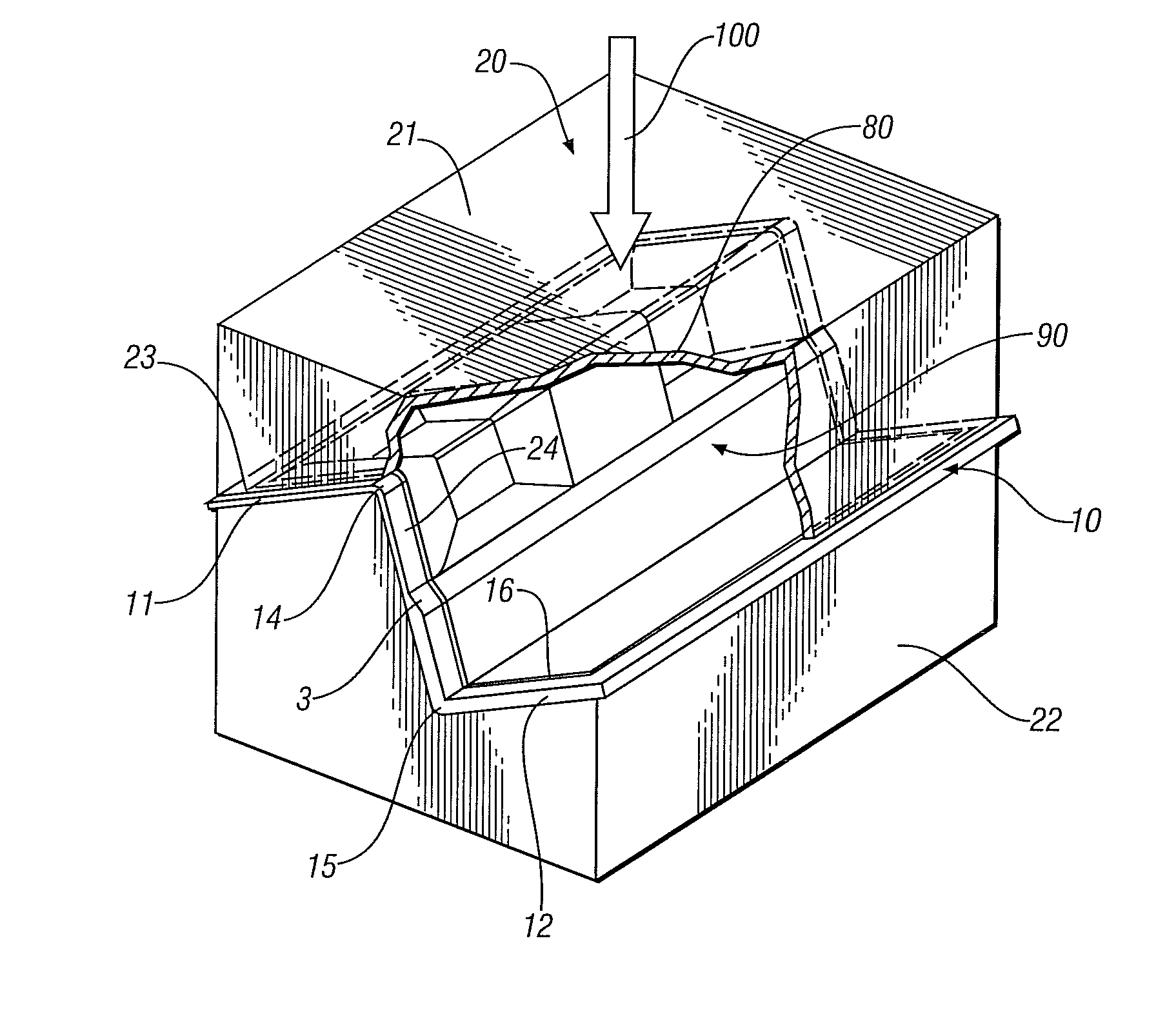
  • Forming of complex shapes in aluminum and magnesium alloy workpieces
  • Forming of complex shapes in aluminum and magnesium alloy workpieces
  • Forming of complex shapes in aluminum and magnesium alloy workpieces

Examples


example 1

A Fender Reinforcement

[0023]In this example an aluminum or magnesium alloy bracket or reinforcement member is made for use, for example, in attaching a polymeric fender to a space frame body structure. Four or more such parts might be used in the making of a vehicle body.

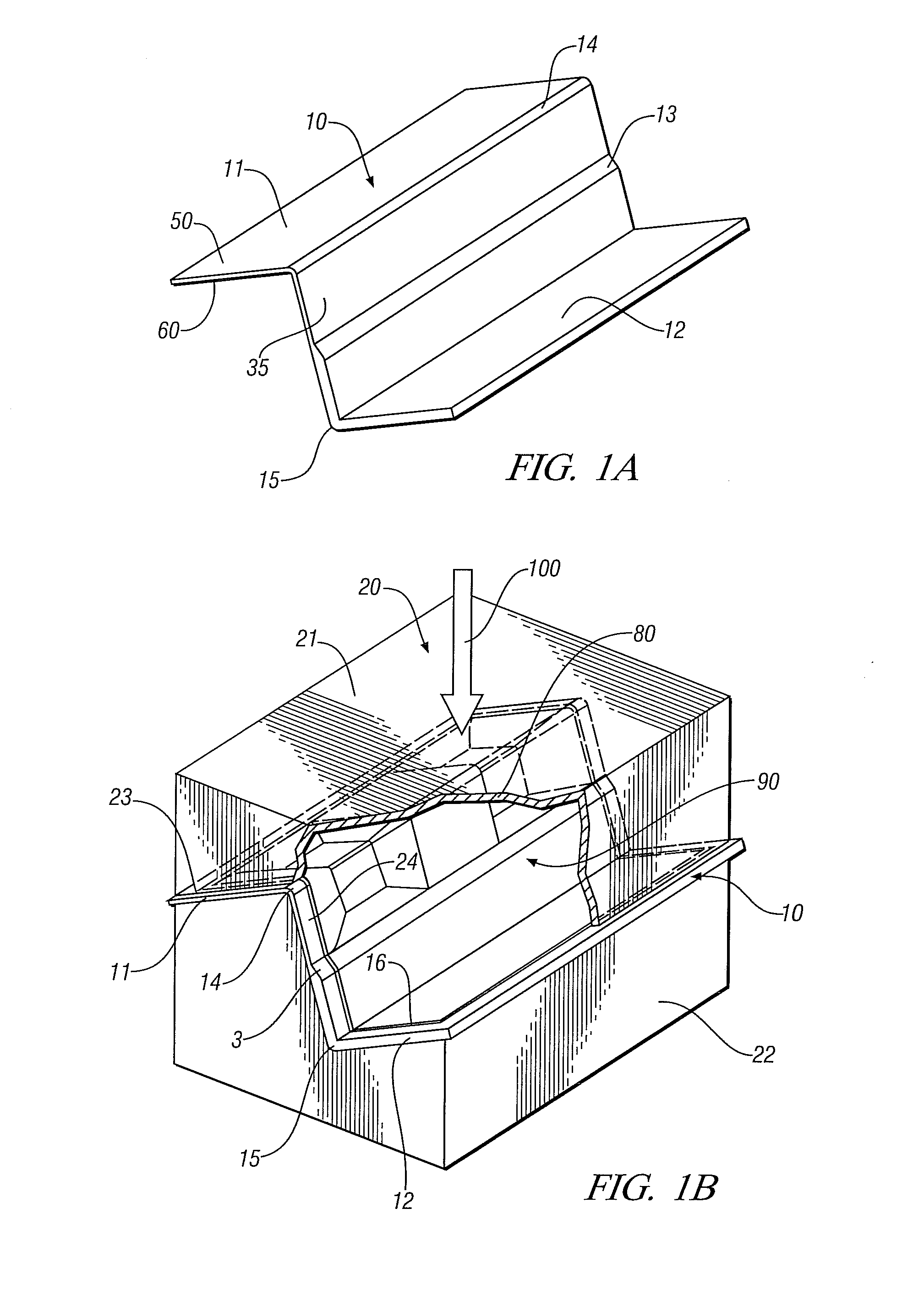
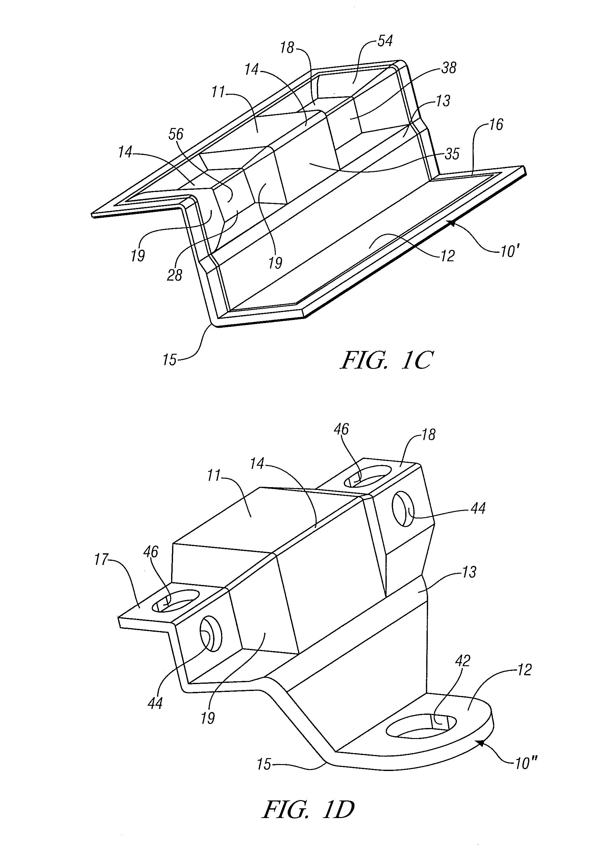
[0024]FIG. 1A shows a section 10 of an extruded form comprising two thicknesses of extrudate and generally resembling the letter “Z”. The extrudate comprises a first segment 11, a second segment 12 and a connecting segment 35 joining segments 11 and 12. The material thickness in segment 12 is greater than the material thickness in segment 11. Connecting segment 35 has a portion comprised of material of thickness corresponding to segment 11 and a portion comprised of material of thickness corresponding to segment 12 with a progressive transition from one thickness to the other in region 13. Segment 11 adjoins segment 35 along line 14 corresponding to a generally 90° change in inclination while segment 12 adjoins tran...

example 2

Bracket

[0032]In this example another aluminum or magnesium alloy bracket or reinforcement member is made for use, for example, in making a vehicle body structure. Several such parts might be used in the making of a vehicle body.

[0033]In Example 1, the extruded blank was used directly and the required trimming was performed subsequent to the forming operation. The extruded blank however may require additional trimming prior to forming to render its shape suitable for the specific forming operation contemplated. In this example, shown in FIG. 2A, the extruded blank 110 has a form generally resembling the letter “L” with a first segment or leg 111 of the “L” being thinner than the second segment or the second leg of the “L”112. In this example the transition from thick section to thin section occurs generally at small radius outer bend 113, the specific location being dictated by the need to achieve a smooth transition from the thick to thin sections and therefore dependent on the spec...

example 3

Case for an Electronic Device

[0038]In this example a pan structure of light weight aluminum or magnesium alloy is made with integral reinforcing or spacing ribs being formed in the base of the pan. The pan may be used as an enclosure for a computer or other electronic device.

[0039]In this example, the extruded blank 210 shown in FIG. 3A comprises a generally flat horizontal base 211 of generally uniform thickness with a plurality of integral, parallel, stiffening features 212 and 213 that extend upwardly from a surface of base 211. Stiffening features 212 and 213 may, as shown, in FIG. 3A and subsequent, be of differing height and will extend along the length of the blank.

[0040]In the configuration shown in FIG. 3A, the blank 210 will be more resistant to deformation in a direction substantially orthogonal to the orientation of ribs 212, 213 and less resistant to deformation in a direction generally aligned with the orientation of ribs 212, 213. To enable more homogenous deformation...


PUM

PropertyMeasurementUnit
temperatureaaaaaaaaaa
temperaturesaaaaaaaaaa

Abstract

A billet of an aluminum alloy or magnesium alloy is formed by a combination of forming operations into a desired article of complex, but open shape. In a first step a billet is heated and extruded to form an extruded workpiece profile having at least first and second sections of different thicknesses. The extruded workpiece may be shaped so that the respective sections are at an angle to each other. The extruded workpiece is then further formed against a forming surface so that the shape of least one of the sections is further formed toward the shape of the article. The methods are suitable for efficient manufacture of many like complex shapes such as brackets and reinforcement members, and even container pans for computers and other electronic devices.

Description

TECHNICAL FIELD[0001]This invention pertains to the forming of articles of complex shapes (including sections with varying thicknesses) in light metal alloy starting materials. More specifically, this invention pertains to the use of a combination of extrusion forming and elevated temperature forming against a die surface to make useful structural parts that are difficult to form (or cannot be made) by a single forming operation.BACKGROUND OF THE INVENTION[0002]There is a desire to reduce weight in many manufactured articles. The need is acute in the manufacture of automotive vehicles but is not limited to such applications. The ability to integrate multiple thicknesses into a single part is useful for minimizing overall part mass without sacrificing strength or stiffness in selected regions. Also thin gage parts, such as sheet metal, frequently afford limited thread engagement, and thus limited holding power, for threaded fasteners. Thus the ability to selectively introduce thicker...

Claims


Application Information

Patent Timeline
Patent Type & Authority Applications(United States)
IPC IPC(8): B21D31/00
CPCB21C23/142B21D53/88B21D22/02
Inventor KLEBER, RICHARD M.KRAJEWSKI, PAUL E.KIM, SOOHOSHINABARKER, CURTIS L.BOSWAY, NICHOLAS M.VOSS, MARK A.PELOWSKI, GARY R.
Owner GM GLOBAL TECH OPERATIONS LLC
Learn More