
Thin film semiconductor device, method of manufacturing the same and display

a thin film semiconductor and manufacturing method technology, applied in thermoelectric devices, instruments, optics, etc., can solve problems such as process complexity, and achieve the effect of improving the characteristics of thin film transistors and improving the electrical characteristics and uniformity of them

Inactive Publication Date: 2007-12-20
SONY CORP
View PDF2 Cites 18 Cited by
  • Summary
  • Abstract
  • Description
  • Claims
  • Application Information

AI Technical Summary

Benefits of technology

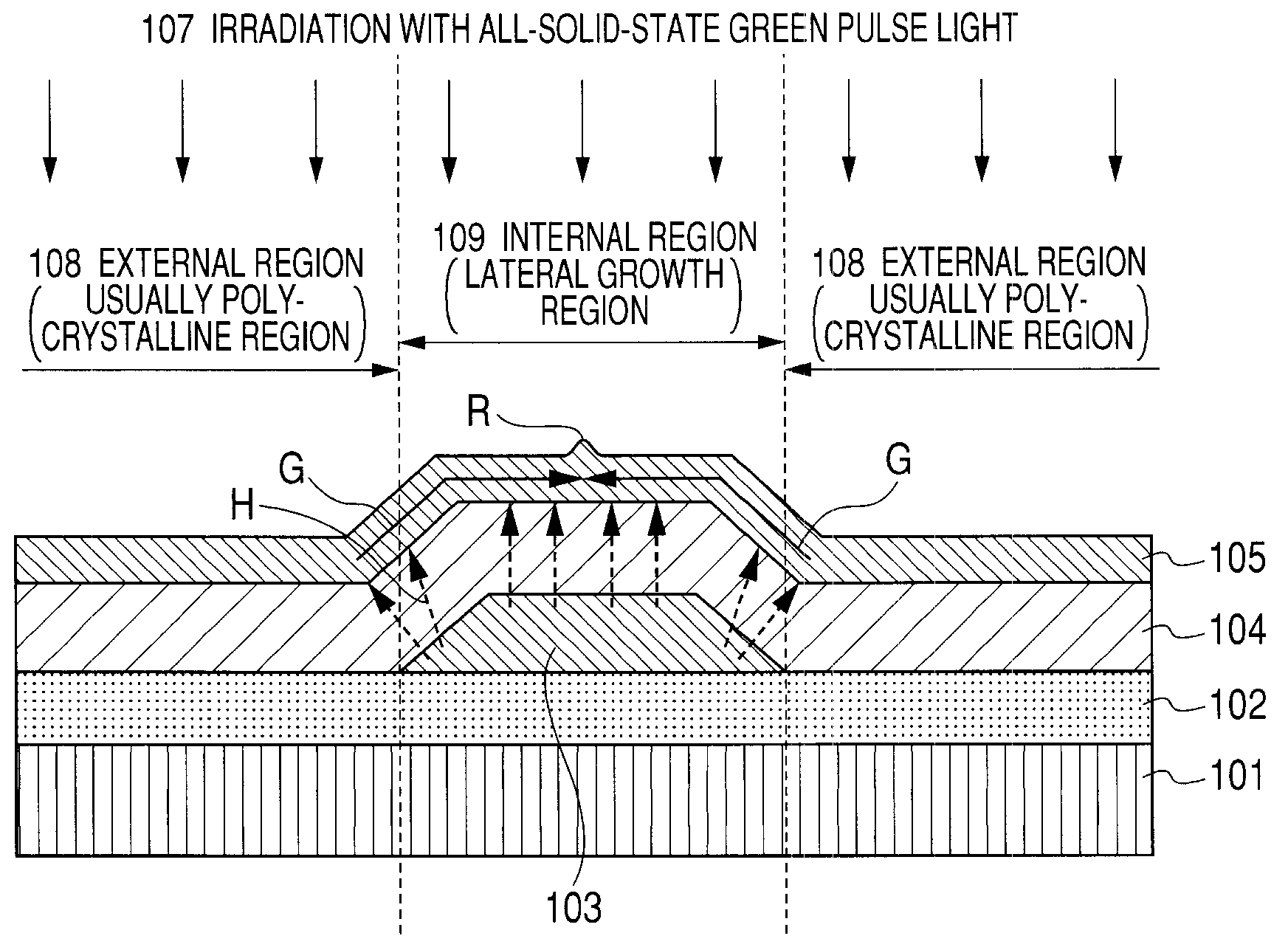
[0019] In the case where the semiconductor thin film is made of silicon or composed of silicon as a major component, since the portion overlapping with the light reflection and absorption layer is selectively melted upon irradiation with laser light and excessive heat energy is not applied to the semiconductor thin film of the external region, it is effective to use laser light having a wavelength ranging from 520 nm to 540 nm. This laser light of a green wavelength is named as a so-called green laser and is characterized in that a light absorptivity of the silicon film is low as compared with an ultraviolet excimer laser. For example, in the case where a thickness of the silicon thin film is not more than 100 nm, the green laser is absorbed only in a proportion of from approximately 5 to 10% by the silicon film. Accordingly, it becomes possible to heat the silicon thin film of the portion overlapping with the light reflection and absorption layer in a high energy density corresponding to reflection by the light reflection and absorption layer and re-incidence on the silicon thin film as compared with other portion. By using this green laser, it becomes possible to selectively melt the internal region of the semiconductor thin film existing inside the gate electrode and subsequently induce lateral crystal growth.
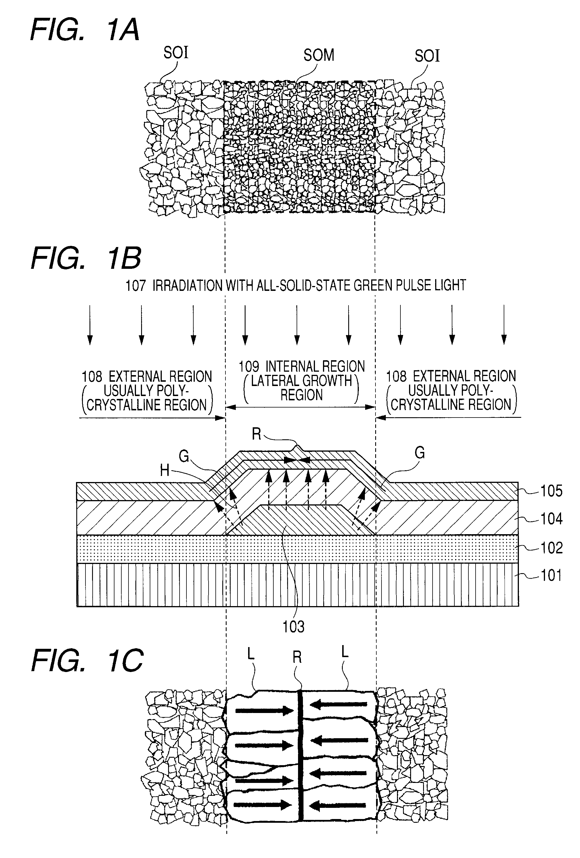
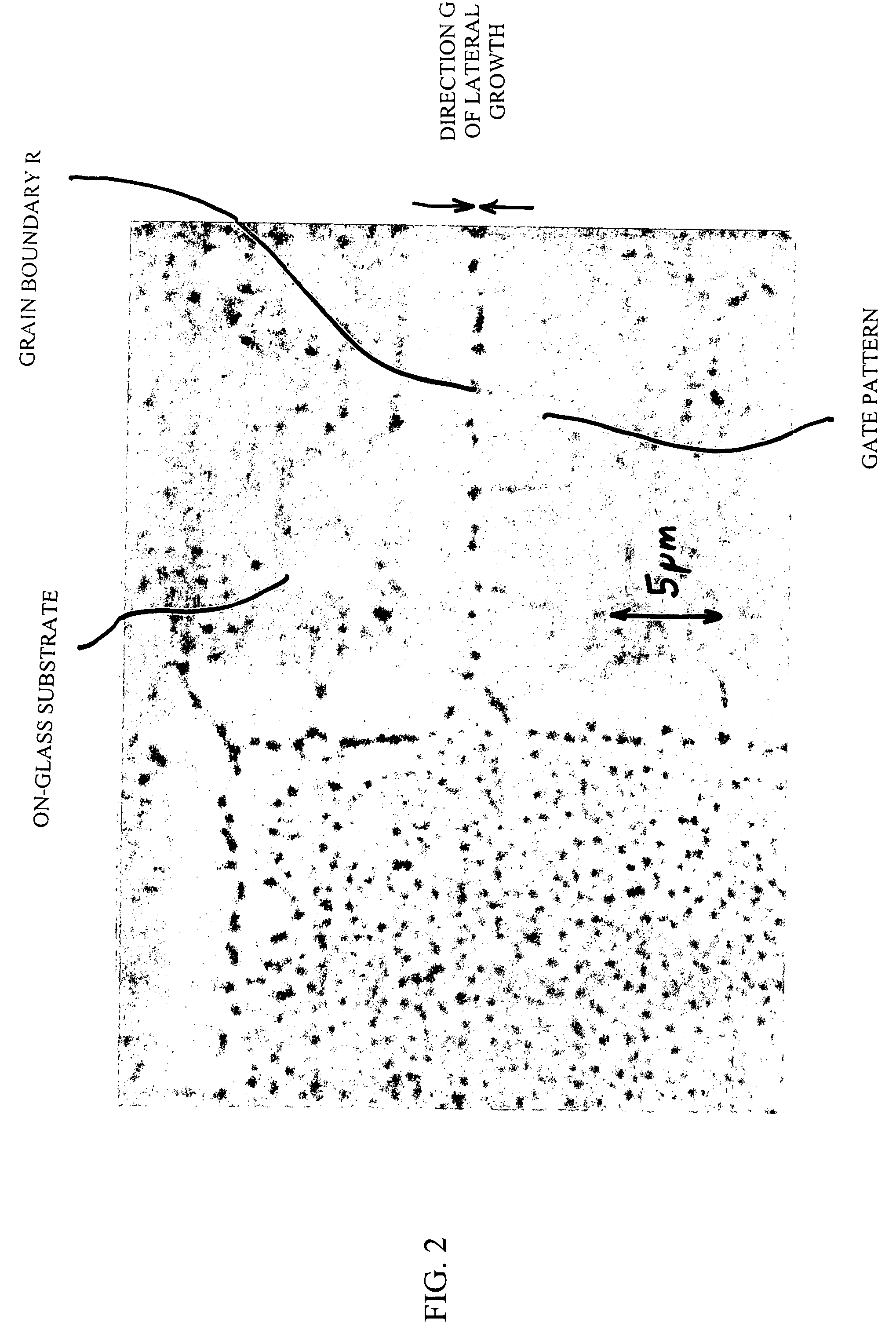
[0021] In accordance with the manufacturing method according to an embodiment of the invention, the lateral crystal growth is controlled pursuant to the pattern of the light reflection and absorption layer to be formed prior to the laser annealing. According to this, it becomes possible to control the size and direction of a polycrystalline silicon grain boundary in the internal region, and electric characteristics and uniformity thereof are remarkably improved. By using this internal region in the channel region of a thin film transistor, it is possible to remarkably improve the characteristics of the thin film transistor.

Problems solved by technology

However, in the lateral crystallization technology disclosed in Patent Document 1, laser light is irradiated twice in total, during which time the crystallization is performed according to the following procedures of (formation of metal mask)→(first irradiation with laser)→(removal of metal mask)→(second irradiation with laser), and therefore, the process becomes complicates.

Method used


Image

  • Thin film semiconductor device, method of manufacturing the same and display
  • Thin film semiconductor device, method of manufacturing the same and display
  • Thin film semiconductor device, method of manufacturing the same and display

Examples


Embodiment Construction

[0032] Embodiments of the invention are hereunder described in detail with reference to the accompanying drawings. FIGS. 1A to 1C are each a schematic view to show a principal part of a manufacturing method of a thin film semiconductor device according to an embodiment of the invention. FIG. 1B shows a schematic cross-sectional view of a semiconductor device; and FIGS. 1A and 1C are each a plan view so show a phase change of a semiconductor thin film appearing in a manufacturing process. Basically, a manufacturing method of a thin film semiconductor device according to an embodiment of the invention includes a light reflection and absorption layer forming step, a patterning step, an insulating film forming step, a semiconductor thin film forming step, and a laser annealing step. As illustrated in FIG. 1B, first of all, in the light reflection and absorption layer forming step, a light reflection and absorption layer 103 is formed on a transparent substrate 101 made of a glass or the...


PUM

PropertyMeasurementUnit
wavelengthaaaaaaaaaa
thicknessaaaaaaaaaa
wavelengthaaaaaaaaaa

Abstract

A method of manufacturing a thin film semiconductor device is disclosed. The method includes the steps of: forming a light reflection and absorption layer for reflecting and absorbing light on a substrate; patterning the light reflection and absorption layer in a prescribed shape; forming an insulating film covering the patterned light reflection and absorption layer; forming a semiconductor thin film containing a polycrystalline grain on the insulating film; and laser annealing the semiconductor thin film by irradiating pulse oscillated laser light to crystallize the semiconductor thin film. The laser annealing step includes a heating process, and a cooling process.

Description

CROSS REFERENCES TO RELATED APPLICATIONS [0001] The present invention contains subjects related to Japanese Patent Application JP 2006-154105 filed in the Japan Patent Office on Jun. 2, 2006, the entire contents of which being incorporated herein by reference. BACKGROUND OF THE INVENTION [0002] 1. Field of the Invention [0003] The invention relates to a thin film semiconductor device and a method of manufacturing the same and to a display of an active matrix type configured of a thin film semiconductor device. In more detail, the invention relates to a crystallization technology of a semiconductor thin film for forming a device region of a thin film semiconductor device. In further detail, the invention relates to a lateral crystal growth technology for applying a temperature difference to different regions of a semiconductor thin film by laser annealing and inducing crystal growth in a planar direction (lateral direction) of the film by utilizing it. [0004] 2. Description of the Re...

Claims


Application Information

Patent Timeline
Patent Type & Authority Applications(United States)
IPC IPC(8): H01L33/00H01L51/52G02F1/13H01L21/20H01L21/336H01L29/786
CPCH01L21/02488H01L21/02491H01L21/02502H01L21/02532H01L27/1296H01L21/02691H01L21/268H01L27/1281H01L21/02686
Inventor ASANO, AKIHIKO
Owner SONY CORP
Learn More