
Internal combustion engine control device

Inactive Publication Date: 2011-03-03
NISSAN MOTOR CO LTD
View PDF10 Cites 1 Cited by
  • Summary
  • Abstract
  • Description
  • Claims
  • Application Information

AI Technical Summary

Benefits of technology

[0006]It is therefore an object of this invention to prevent combustion instability and noise generation caused by a valve timing setting at the time of an engine restarting operation.

Problems solved by technology

If the engine is restarted in this state, the engine is restarted at a cam phase before the valve timing reaches the target angle, and therefore combustion in the engine becomes unstable.
Furthermore, the oil pressure does not increase immediately after the restarting operation, and therefore a vane in the variable valve mechanism may not be able to follow a rotation of a cam sprocket.
Accordingly, the vane may collide with an interior wall surface or the like, leading to noise generation.
However, the prior art described above does not disclose control of the variable valve mechanism when an engine operation is stopped.

Method used


Image

  • Internal combustion engine control device
  • Internal combustion engine control device
  • Internal combustion engine control device

Examples


Embodiment Construction

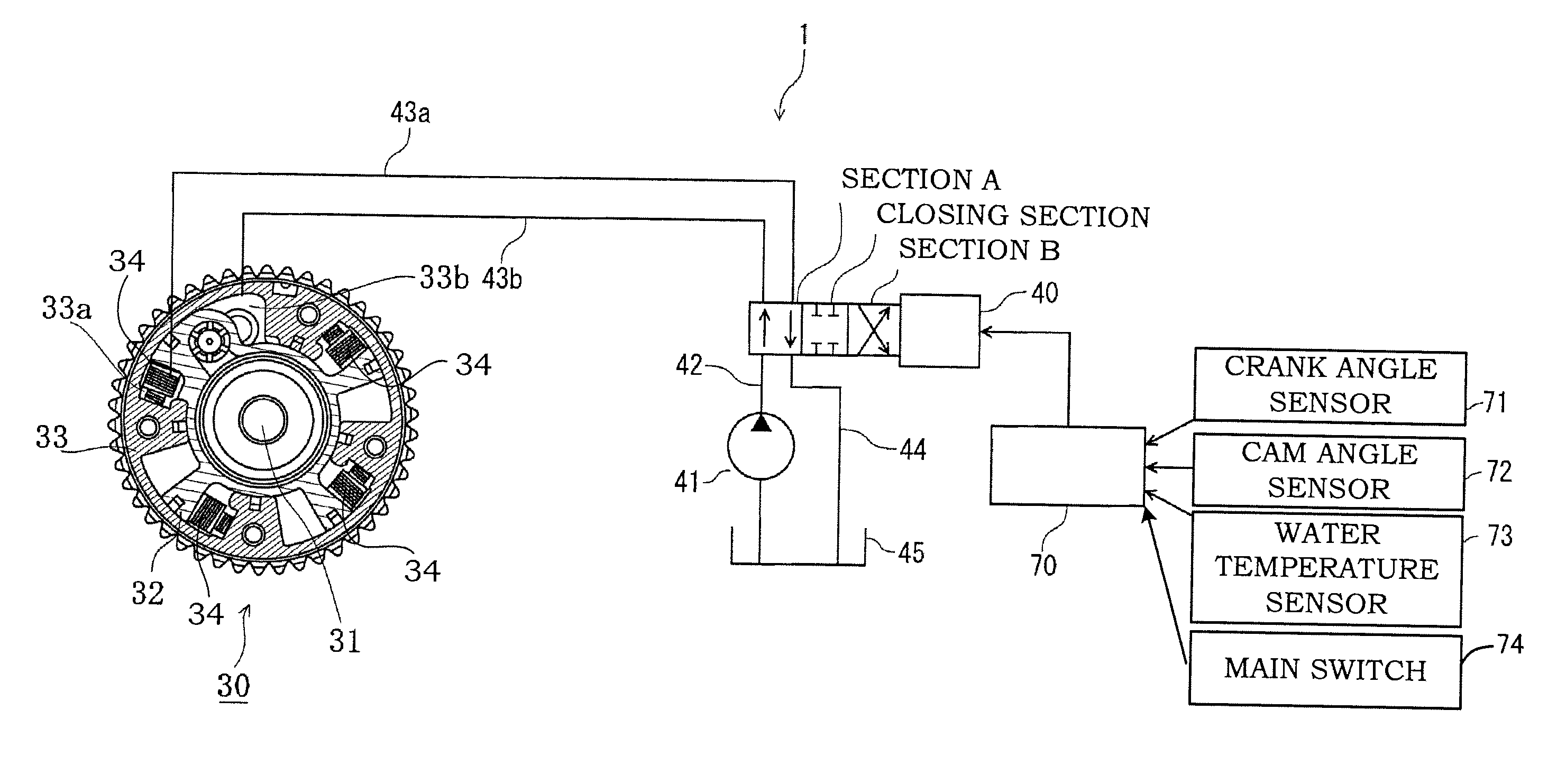
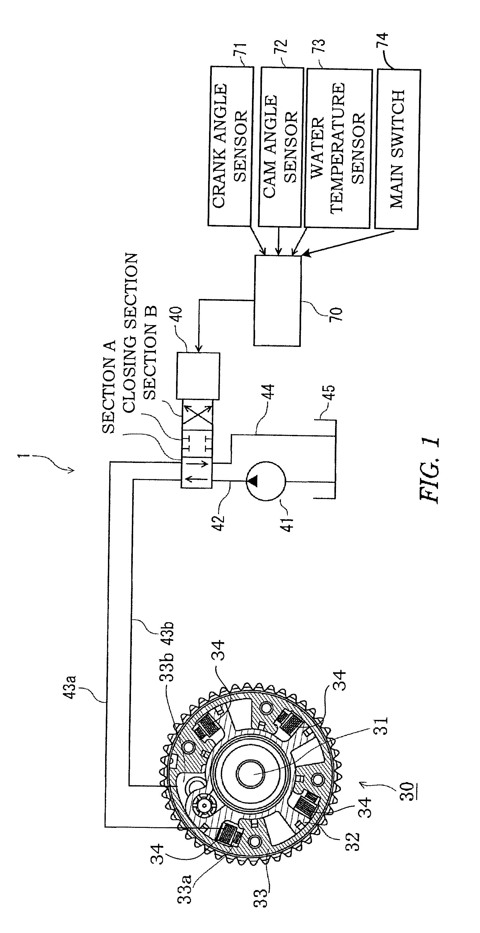
[0013]Referring to FIG. 1 of the figures, a control device 1 for a vehicle internal combustion engine according to this invention comprises a variable valve mechanism 30, a solenoid valve 40 that operates the variable valve mechanism 30 using oil discharged from an oil pump 41, and a controller 70 that switches the solenoid valve 40.

[0014]The engine comprises a cam shaft 31, and a cam shaft driving sprocket (to be referred to hereafter as a “sprocket”) 33 that is coaxial with the cam shaft 31 and rotates in synchronization with a crankshaft of the engine via a belt or a chain. The control device 1 uses oil pressure to advance / retard an opening / closing timing of an exhaust valve by modifying a relative phase angle (to be referred to hereafter as a “conversion angle”) between the cam shaft 31 and the cam shaft driving sprocket 33.

[0015]The variable valve mechanism 31 includes a plurality of vanes (four in FIG. 1) 32 that rotate integrally with the cam shaft 31. It should be noted that...


PUM


Abstract

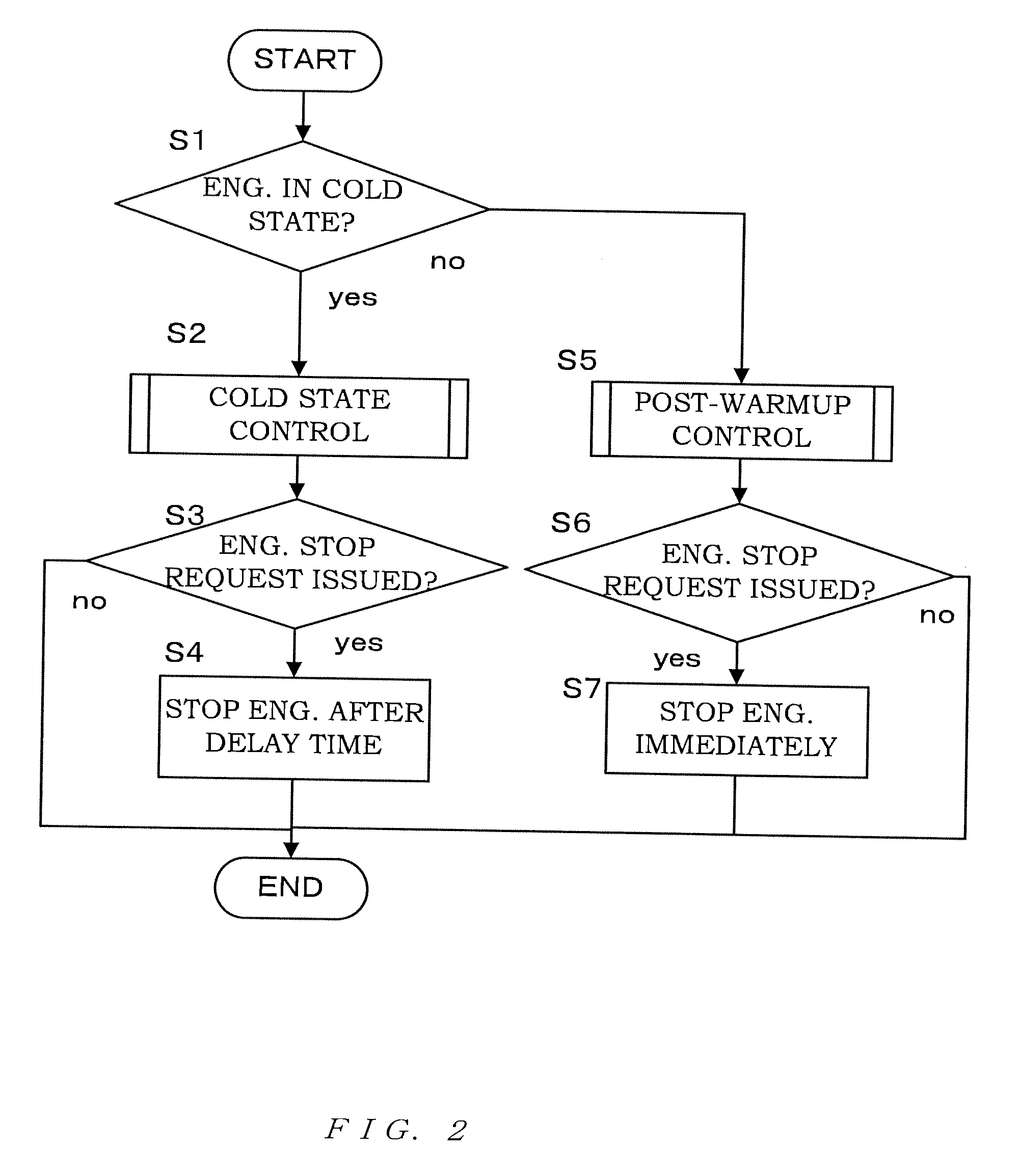
A variable valve mechanism provided on a exhaust side of an internal combustion engine, in which a most advanced state is set as an initial state, operating condition detecting means for detecting operating conditions, variable valve control means for controlling an operation of the variable valve mechanism in accordance with the operating conditions, engine condition determining means for determining whether the internal combustion engine is in a cold state or a warm state, and stop request determining means for determining whether or not a stop request has been issued in relation to the internal combustion engine are provided. When a stop request is issued in the cold state, the internal combustion engine is stopped after returning the variable valve mechanism to the initial state.

Description

TECHNICAL FIELD[0001]This invention relates to control of an internal combustion engine having a variable valve mechanism on a exhaust side.BACKGROUND ART[0002]A conventional variable valve mechanism varies an opening / closing timing (valve timing) of an intake valve or an exhaust valve to improve an output performance, an emission performance, and a fuel efficiency performance of an internal combustion engine for a vehicle.[0003]For example, JP06042379A, published by the Japan Patent Office in 1994, discloses a technique of reducing an HC discharge amount by performing control to increase an overlap period between an intake valve open period and an exhaust valve open period when an engine is cold using a variable valve mechanism driven by oil pressure.DISCLOSURE OF THE INVENTION[0004]Incidentally, when an engine is stopped during a valve timing modification operation in a hydraulic variable valve mechanism, the oil pressure decreases as the engine is stopped, and as a result, the va...

Claims


Application Information

Patent Timeline
IPC IPC(8): F01L1/34
CPCF01L1/022Y02T10/18F01L1/3442F01L2001/34426F01L2001/34469F01L2001/34479F01L2001/34483F01L2800/02F01L2800/03F02D13/0219F02D13/0249F02D13/0261F02D13/08F02D41/042F02D41/068F02D2013/0292F01L1/024Y02T10/12
Inventor MIURA, HAJIME
Owner NISSAN MOTOR CO LTD
Learn More