Coal-burning boiler coupling biomass fuel gas combustion device and combustion system arrangement method using same

A biomass gas and combustion device technology, applied in the direction of combustion methods, combustion using gaseous fuels and powder fuels, and controlled combustion, can solve the effects of fuel burnout nitrogen oxide emissions, boiler efficiency, combustion aerodynamic field, Does not have low nitrogen capacity and other issues, and achieves the effect of wide load adaptability, low emission concentration, and sufficient combustion

Pending Publication Date: 2020-01-17
HARBIN BOILER
View PDF0 Cites 1 Cited by
  • Summary
  • Abstract
  • Description
  • Claims
  • Application Information

AI Technical Summary

Problems solved by technology

[0002] In the biomass gasification coupled coal-fired unit power generation system, due to the change of the type of biomass fuel and the operating conditions of the gasifier itself, the composition of the gas produced by the gasifier is unstable, the calorific value fluctuates greatly, and a large amount of low calorific value gas is injected After entering the furnace, if the combustion conditions are unfavorable, it may have a great impact on the combustion aerodynamic field in the furnace, which in turn affects the burnout of fuel, the emission of nitrogen oxides and the efficiency of the boiler
At present, the existing biomass gas burners are mainly designed for biomass gas with stable gas composition and fixed calorific value. Most of them have complex structures and are mostly used for gas furnaces that purely burn biomass gas. Generally, they do not have low-nitrogen capabilities.

Method used


Image

  • Coal-burning boiler coupling biomass fuel gas combustion device and combustion system arrangement method using same
  • Coal-burning boiler coupling biomass fuel gas combustion device and combustion system arrangement method using same
  • Coal-burning boiler coupling biomass fuel gas combustion device and combustion system arrangement method using same

Examples


Embodiment Construction

[0014] The present invention will be described in further detail below in conjunction with the accompanying drawings: the present embodiment is implemented on the premise of the technical solution of the present invention, and detailed implementation is provided, but the protection scope of the present invention is not limited to the following embodiments.

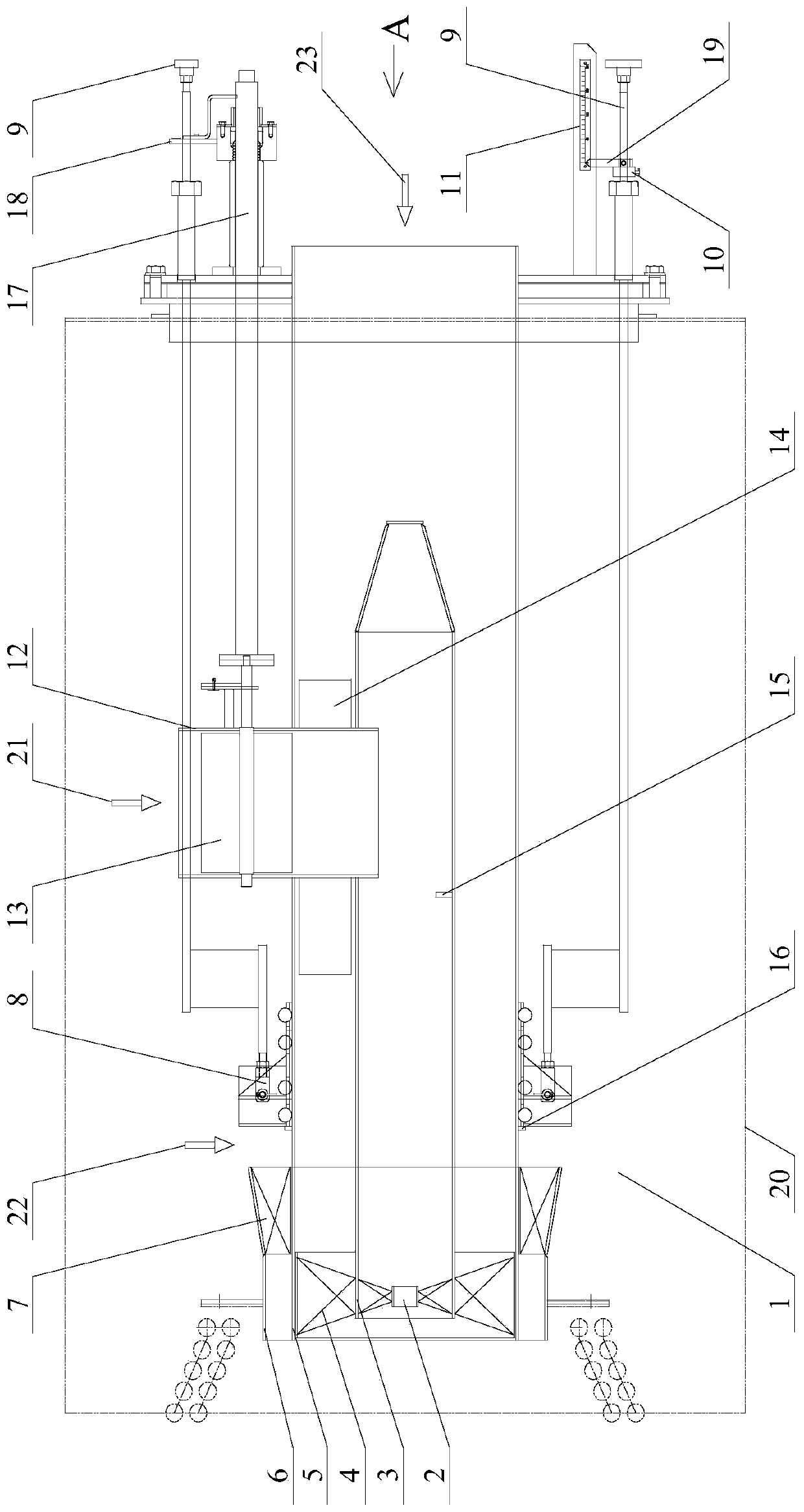
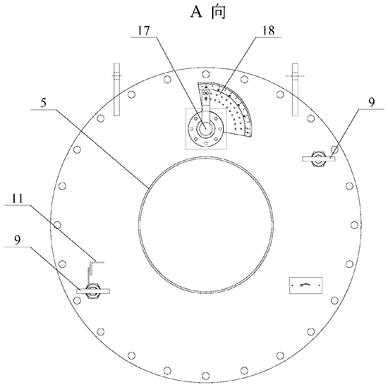
[0015] Such as figure 1 and figure 2 As shown, a coal-fired boiler coupling biomass gas combustion device involved in this embodiment includes: a biomass gas combustion device 1, a central air swirl device 2, a central air cylinder 3, a gas swirl device 4, and a gas channel 5. Secondary air pipe 6. Secondary air swirl device 7. Secondary air door adjustment mechanism 8. Secondary air door adjustment rod 9. Positioner 10. Secondary air door indicator scale 11. Central air introduction channel 12. Central air volume adjustment Baffle plate 13, conical blunt body 14, central wind block 15, secondary air volume adjustment de...


PUM


Abstract

The invention provides a coal-burning boiler coupling biomass fuel gas combustion device and a combustion system arrangement method using the coal-burning boiler coupling biomass fuel gas combustion device, and belongs to the technical field of boiler combustion devices and the combustion system arrangement methods of the coal-burning boiler coupling biomass fuel gas combustion devices. A biomassfuel gas combustion device is arranged inside a bellow. A central ventilator is fixed inside a fuel gas channel. The central ventilator and the fuel gas channel are concentrically arranged. A secondary air duct is fixed on the outside of the back end of the fuel gas channel. The secondary air duct and the fuel gas channel are concentrically arranged. A secondary wind swirl device is fixed on an air inlet end of the secondary air duct. A central wind swirl device is installed at the back end inside the central ventilator. A fuel gas swirl device is arranged between the back end of the fuel gaschannel and the back end of the central ventilator. A central wind inlet channel is fixed in the center of the fuel gas channel in forward and backward direction and communicates with the central ventilator. According to the combustion system arrangement method using the coal-burning boiler coupling biomass fuel gas combustion device, the biomass fuel gas combustion device is arranged between an upper pulverized coal burner and an OFA burner.

Description

technical field [0001] The invention relates to a coal-fired boiler coupling biomass gas combustion device and a combustion system arrangement method thereof, and belongs to the technical field of a boiler combustion device and a combustion system arrangement method thereof. Background technique [0002] In the biomass gasification coupled coal-fired unit power generation system, due to the change of the type of biomass fuel and the operating conditions of the gasifier itself, the composition of the gas produced by the gasifier is unstable, the calorific value fluctuates greatly, and a large amount of low calorific value gas is injected After entering the furnace, if the combustion conditions are unfavorable, it may have a great impact on the combustion aerodynamic field in the furnace, which in turn affects the burnout of fuel, the emission of nitrogen oxides and the efficiency of the boiler. At present, the existing biomass gas burners are mainly designed for biomass gas w...

Claims


Application Information

Patent Timeline
Patent Type & Authority Applications(China)
IPC IPC(8): F23C1/12F23C7/00F23L9/00F23L15/00F23N3/00
CPCF23C1/12F23C7/002F23C7/008F23L9/00F23L15/00F23N3/00Y02E20/34
Inventor 徐彦辉王静杰于强孙浩于景泽关靖宇魏国华
Owner HARBIN BOILER
Why Eureka
Try Eureka