Al technical title is built by PatSnap Al team. It summarizes the technical point description of the patent document.
a split wedge and single-post technology, applied in wood splitting, multi-purpose machines, manufacturing tools, etc., can solve the problems of insufficient support, insufficient power, and insufficient power, and achieve the effect of less power
Inactive Publication Date: 2011-03-03
HICKS NORMAN A
View PDF7 Cites 7 Cited by
Summary
Abstract
Description
Claims
Application Information
AI Technical Summary
This helps you quickly interpret patents by identifying the three key elements:
Problems solved by technology
Method used
Benefits of technology
[0021]Page 2, FIG. 8 This is the six-way wedge. Because these blades are supported right at their bases, they do not need to be as massive as with other split wedge designs. This allows them to split the wood cleanly yet with less power needed.
Problems solved by technology
These improve the efficiency of splitting by doing multiple splits on each pass, but add the problem of holding the extra blades in place against 22 to 31 tons of hydraulic pressure.
Mostly these are not designed for or good for supporting slip over four-way or six-way wedges.
This system is not good because it very soon jams into the sharp blade of the two-way wedge, dulls it, and also is not readily capable of being raised or lowered frequently which is necessary to accommodate the different diameter logs being split.
This would not work well if the operator wanted to use a self-loading system such as an elevator to load the split pieces of wood,
The other problem is how to regulate the height of the four-way and six-way wedges.
However, this system requires those wedges to be lifted off the support bar and replaced for each change of height.
This is a very slow system though initially quite inexpensive.
This system is very fast and precise but is expensive to install.
Method used
Image
Click on the blue label to locate the original text in one second.
Reading with bidirectional positioning of images and text.
Examples
Embodiment Construction
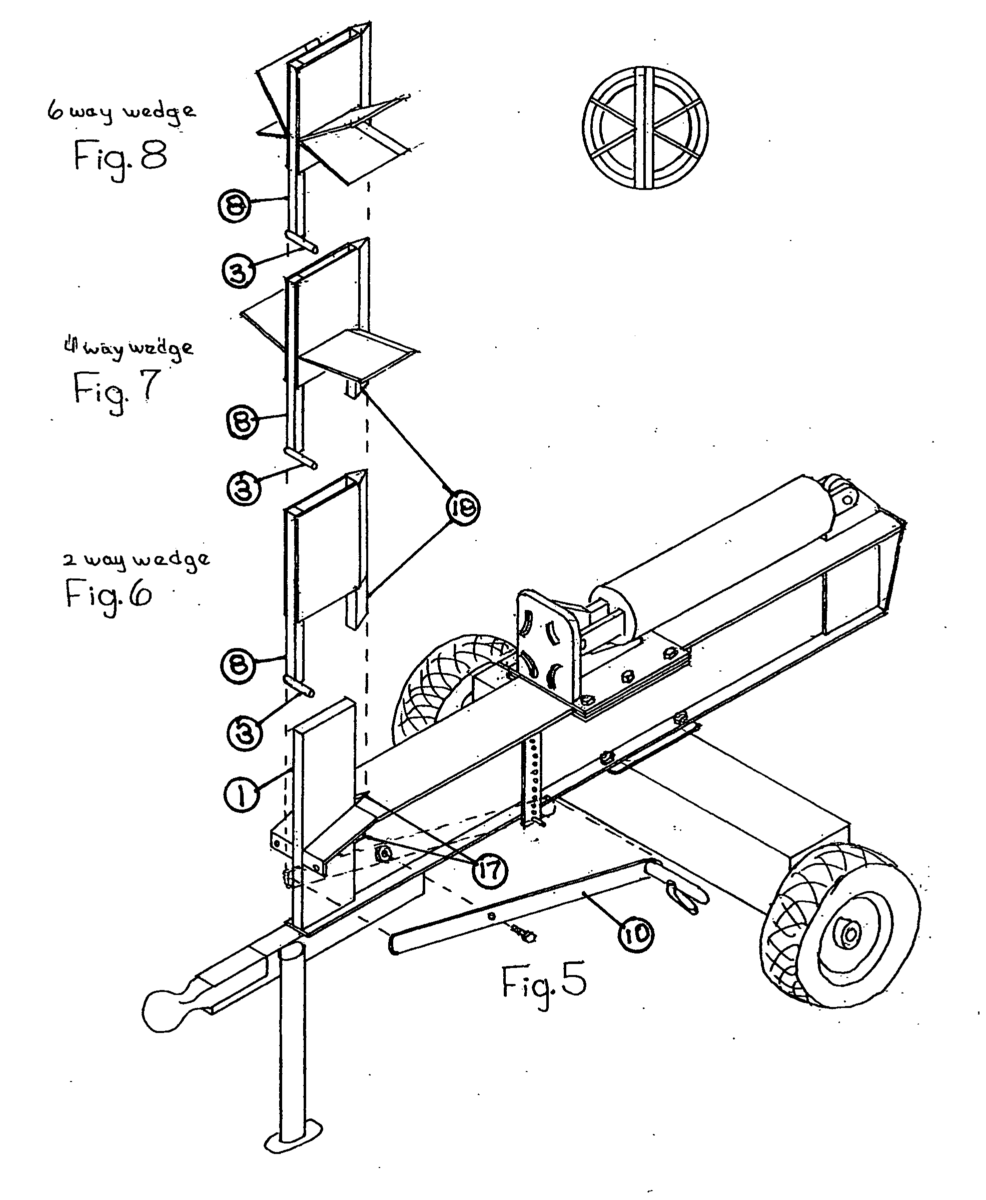
[0022]First of all, this basic design of splitter is the standard design of most splitters.
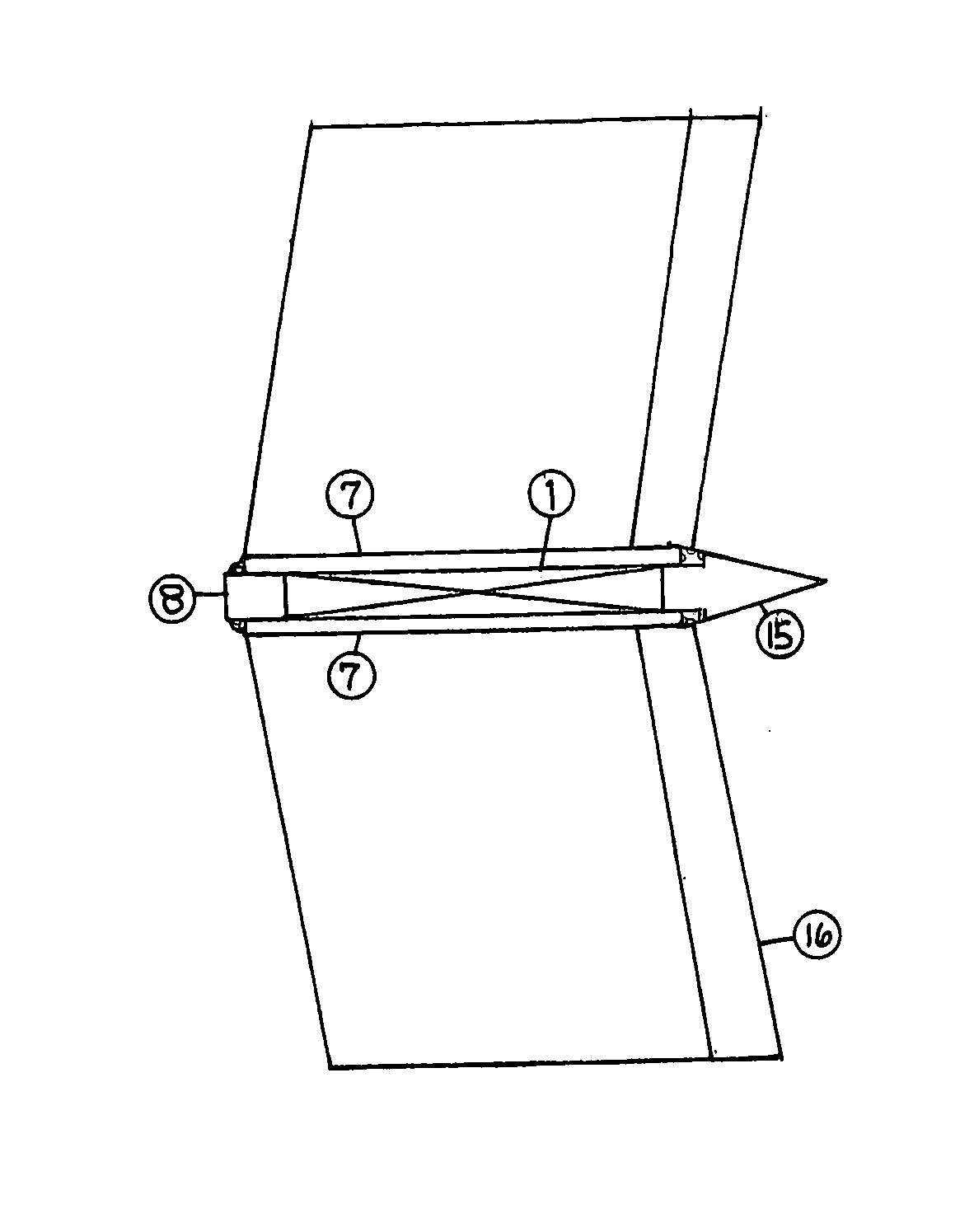
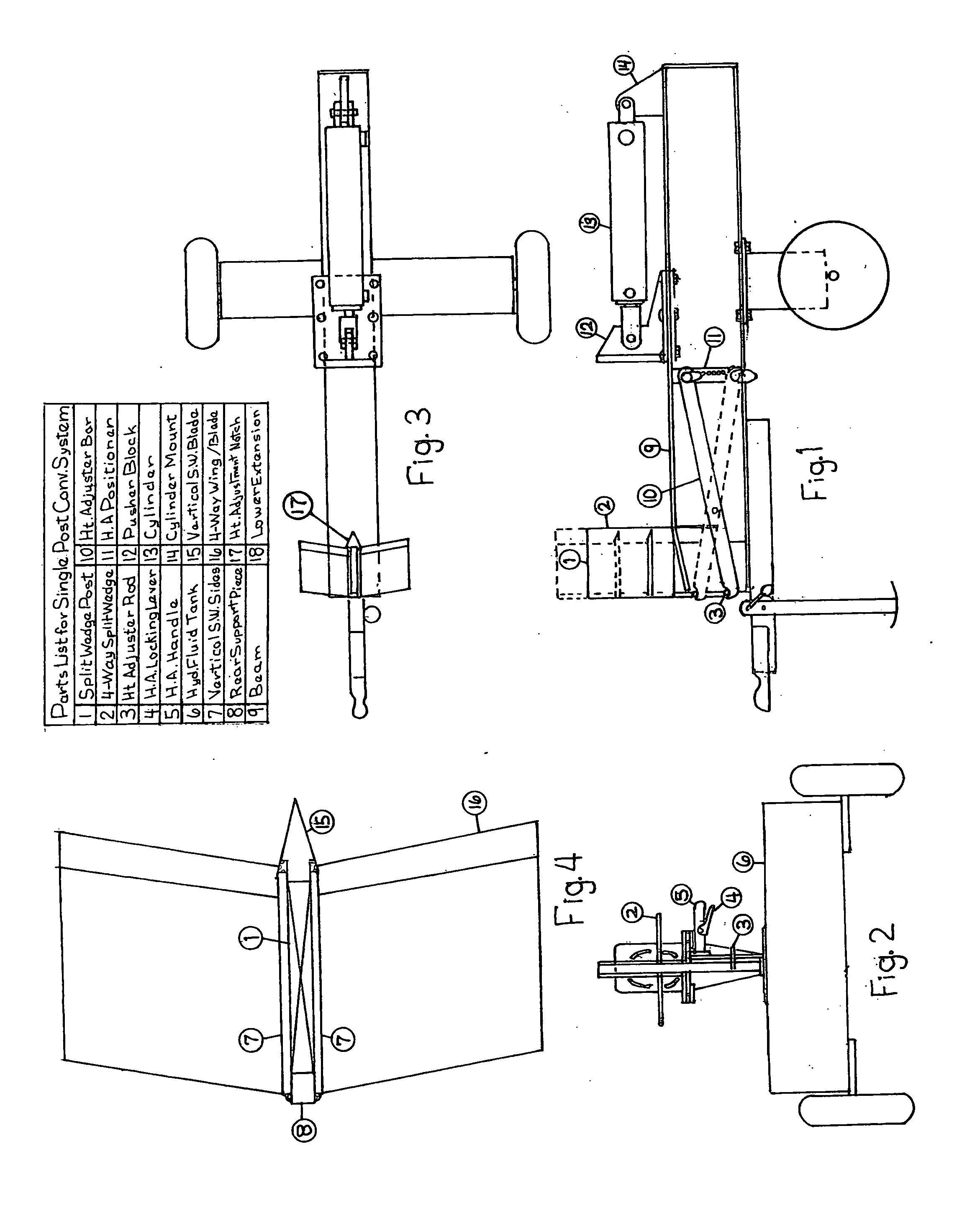
[0023]The differences are, first, in the beam. In this plan it is 11 inches high though the design is not limited to these dimensions. This extra height is necessary to be strong enough to withstand the enormous pressures against the split wedges that are a minimum of 12 inches high and can be raised up to 16 inches high. The beam is notched to accommodate the Split Wedge Post and the cutting edge extensions of the split wedges. The Split Wedge Post (FIGS. 5, 1, No. 1) is angled forward slightly (about 5 degrees here) to keep the logs from raring up as they are forced into the split wedges.
[0024]The pusher block is built of standard construction with spacers and holders bolted to the bottom plate to hold it in place. A large ¾×7×10 HR flat is used for the actual pusher block. It is backed by a 1×10×10 piece of HR flat with a 1 inch hole to attach to the cylinder. Small pieces of steel are weld...
PUM
Abstract
This log splitter is designed to work very fast and efficiently, yet be less expensive to construct than comparable splitters. By using a single, vertical, rectangular post to support all the split wedges including the two-way, these wedges can be of a simpler, less expensive, yet as strong construction. Secondly, by angling the Split Wedge Post slightly forward, it retains the split wedges during splitting operations, limits them to rise only slightly as the wood passes through, yet allows them to be freely and easily placed and removed by hand by the operator. The manually operated Height Adjuster Bar located conveniently on the side of the beam, allows the operator to easily and quickly raise and lower the split wedges as necessary to accommodate different sized logs and to retain the wedges in place with a simple latch type arrangement.
Description
CROSS-REFERENCE TO RELATED APPLICATIONSU.S. Patent Documents[0001]4,353,401Oct. 12, 1982Schilling4,391,312Jul. 5, 1983Sakraida4,860,806Aug. 29, 1989Brace5,337,810Aug. 16, 1994McCormack5,957,175Sep. 28, 1999Smith6,991,010Jan. 31, 2006Smith7,108,029Sep. 19, 2006Albright7,134,464Nov. 14, 2006Walker et alSTATEMENT REGARDING FEDERALLY SPONSORED RESEARCH OR DEVELOPMENT[0002]Not ApplicableREFERENCE TO SEQUENCE LISTING, A TABLE, OR A COMPUTER PROGRAM LISTING COMPACT DISC APPENDIX[0003]not ApplicableBACKGROUND OF THE INVENTION[0004]Log splitters of various sorts have been around for a long time. Hydraulically powered splitters have become the most common type of log splitter. The relatively slow speed but high power of hydraulic cylinders makes them the best choice for splitters. To improve the speed and efficiency of log splitters, four-way, six-way, and even more than six-way split wedges have been added. These improve the efficiency of splitting by doing multiple splits on each pass, but ...
Claims
Application Information
Patent Timeline
Application Date:The date an application was filed.
Publication Date:The date a patent or application was officially published.
First Publication Date:The earliest publication date of a patent with the same application number.
Issue Date:Publication date of the patent grant document.
PCT Entry Date:The Entry date of PCT National Phase.
Estimated Expiry Date:The statutory expiry date of a patent right according to the Patent Law, and it is the longest term of protection that the patent right can achieve without the termination of the patent right due to other reasons(Term extension factor has been taken into account ).
Invalid Date:Actual expiry date is based on effective date or publication date of legal transaction data of invalid patent.
Patent Type & Authority Applications(United States)