Article for Magnetic Heat Exchange and Method for Manufacturing an Article for Magnetic Heat Exchange

Inactive Publication Date: 2011-03-03
VACUUMSCHMELZE GMBH & CO KG
View PDF40 Cites 101 Cited by
  • Summary
  • Abstract
  • Description
  • Claims
  • Application Information

AI Technical Summary

Benefits of technology

[0011]The article may be used as the magnetic refrigerant or magnetic working medium of a magnetic heat exchange system. Providing the article with an anisotropic average thermal conductivity has the advantage that heat generated within the article due to the magnetocaloric effect can be conducted to the surface of the article anisotropically. The heat exchange between the article and a cooling or heat exchange medium which surrounds the article may be anisotropic as well. As used herein, the terms “coolant” or “coolant medium” and “heat exchange medium,” are used interchangeably irrespective of whether the article is used to supply heat to, or remove heat from, the heat exchange medium or working fluid.
[0012]The article may be arranged in the magnetic heat exchange system so that the most efficient thermal transfer occurs in directions perpendicular to the direction of cool

Problems solved by technology

The poorer thermal conductivity of the article in the direction of the coolant flow hinders the transfer of the heat in

Method used


Image

  • Article for Magnetic Heat Exchange and Method for Manufacturing an Article for Magnetic Heat Exchange
  • Article for Magnetic Heat Exchange and Method for Manufacturing an Article for Magnetic Heat Exchange
  • Article for Magnetic Heat Exchange and Method for Manufacturing an Article for Magnetic Heat Exchange

Examples


second embodiment

[0103]In the second embodiment illustrated in FIG. 4, the grains 14 of the magnetocalorically passive phase 13 also have a generally plate-like form. The grains 14 are also arranged in the article 1 with a preferred orientation such that their long direction 15 extends in directions generally parallel to the second length b of the article 1 and in directions generally perpendicular to the coolant flow direction 3.

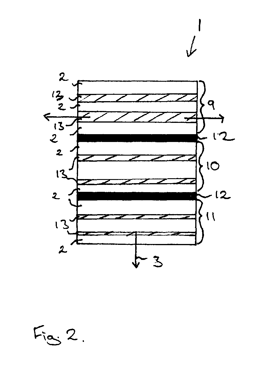
[0104]In the second embodiment of FIG. 4, as in the embodiment of FIG. 2, the anisotropic thermal conductivity of the article 1 is provided by a layered structure in which layers 18 consisting essentially of a magnetocalorically active phase 2 are interleaved with layers 19 consisting essentially of a magnetocalorically passive phase 13. In the embodiment illustrated in FIG. 4, the anisotropic average thermal conductivity of the article 1 is provided macroscopically.

[0105]A single layer 19 of a magnetocalorically passive phase 13 sandwiched between two layers 18 of magnetoc...

fourth embodiment

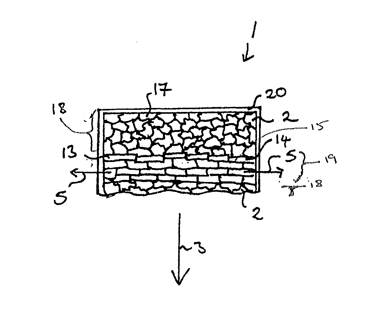
[0116]FIG. 6 illustrates an embodiment of an article 1 for use as the working component of a magnetic heat exchange system according to a

[0117]The article 1 of the fourth embodiment comprises a plurality of grains 17 of a magnetocalorically active phase 2 and a plurality of grains 14 of a magnetocalorically passive phase 13. For illustrative purposes only, the grains 17 are unshaded and the grains 14 are shaded black. On average, each of the grains 14 and / or 17 has a shape which is generally isotropic (e.g., generally spherical). In this embodiment, the article 1 has anisotropic thermal conductivity due to the preferred orientation of the isotropically-shaped grains 14 of the magnetocalorically passive phase 13.

[0118]The generally spherical grains 14 of the magnetocalorically passive phase 13 comprises a ferromagnetic material, in this case iron. The grains 14 are arranged in a plurality of rows or chains 24 having a long direction which extends in directions generally parallel to t...

fifth embodiment

[0123]FIG. 7 illustrates an article 1′ for use as the working component of a magnetic heat exchange system according to a

[0124]The article 1′ of the fifth embodiment consists essentially of one or more magnetocalorically active phases 2. For purposes of illustration, these phases are depicted as unshaded areas. The article 1′ of the fifth embodiment is free from magnetocalorically passive phases. The anisotropic average thermal conductivity of the article 1′ is provided, in this embodiment, by an anisotropic distribution of the density of the article 1′ and, in particular, and anisotropic distribution of the porosity of the article 1′.

[0125]The article 1′ of the fifth embodiment includes a plurality of layers of which five are illustrated in FIG. 7. Three first layers 25 have a relatively low porosity and two second layers 26, which are arranged between adjacent first layers 25, include a higher degree of porosity than that of the first layers 25. In the illustration of FIG. 7, the ...


PUM

PropertyMeasurementUnit
Timeaaaaaaaaaa
Temperatureaaaaaaaaaa
Thicknessaaaaaaaaaa

Abstract

An article (1) for magnetic heat exchange extends in a first direction (3) and in a second direction (5) generally axially perpendicular to said first direction (3). The article (1) comprises at least one magnetocalorically active phase (2). The average thermal conductivity of the article (1) is anisotropic.

Description

BACKGROUND[0001]1. Field[0002]Disclosed herein is an article for magnetic heat exchange and methods for manufacturing an article for magnetic heat exchange.[0003]2. Description of Related Art[0004]The magnetocaloric effect describes the adiabatic conversion of a magnetically induced entropy change to the evolution or absorption of heat. By applying a magnetic field to a magnetocaloric material, an entropy change can be induced which results in the evolution or absorption of heat. This effect can be harnessed to provide refrigeration and / or heating.[0005]In recent years, materials such as La(Fe1-aSia)13, Gd5(Si, Ge)4, Mn (As, Sb) and MnFe(P, As) have been developed which have a Curie Temperature, Tc, at or near room temperature. The Curie Temperature translates to the operating temperature of the material in a magnetic heat exchange system. Consequently, these materials are suitable for use in applications such as building climate control, domestic and industrial refrigerators and fr...

Claims


Application Information

Patent Timeline
IPC IPC(8): F28F7/00B21D53/02
CPCF25B21/00F25B2321/002Y10T29/4935Y02B30/66H01F1/012Y02B30/00H01F1/00H01F1/12
Inventor REPPEL, GEORG WERNERKATTER, MATTHIAS
Owner VACUUMSCHMELZE GMBH & CO KG
Why Eureka
Try Eureka