Active electronically steered cathode emission

a technology of electronic steered cathode and emission site, which is applied in the direction of traveling-wave tubes, electric discharge tubes, tubes with multiple resonators, etc., can solve the problems of exceedingly tight power supply regulation, unsuitable applications, and degrading the quality of electron beams, and achieves greater control over emission sites.

Active Publication Date: 2011-03-03
L3 TECH INC
View PDF9 Cites 2 Cited by
  • Summary
  • Abstract
  • Description
  • Claims
  • Application Information

AI Technical Summary

Benefits of technology

[0014]In another embodiment of an AESC in accordance with the present invention, one or both of the RF signals input into the cavity are comprised of a Fourier sum of harmonic frequency components. If the cavity is designed so that these harmonic frequency components excite spatial harmonics o

Problems solved by technology

However, applying bending fields tends to degrade the quality of the electron beam, making it unsuitable in applications that require precise control of the beam trajectory, such as in high-frequency devices where cir

Method used


Image

  • Active electronically steered cathode emission
  • Active electronically steered cathode emission
  • Active electronically steered cathode emission

Examples


Embodiment Construction

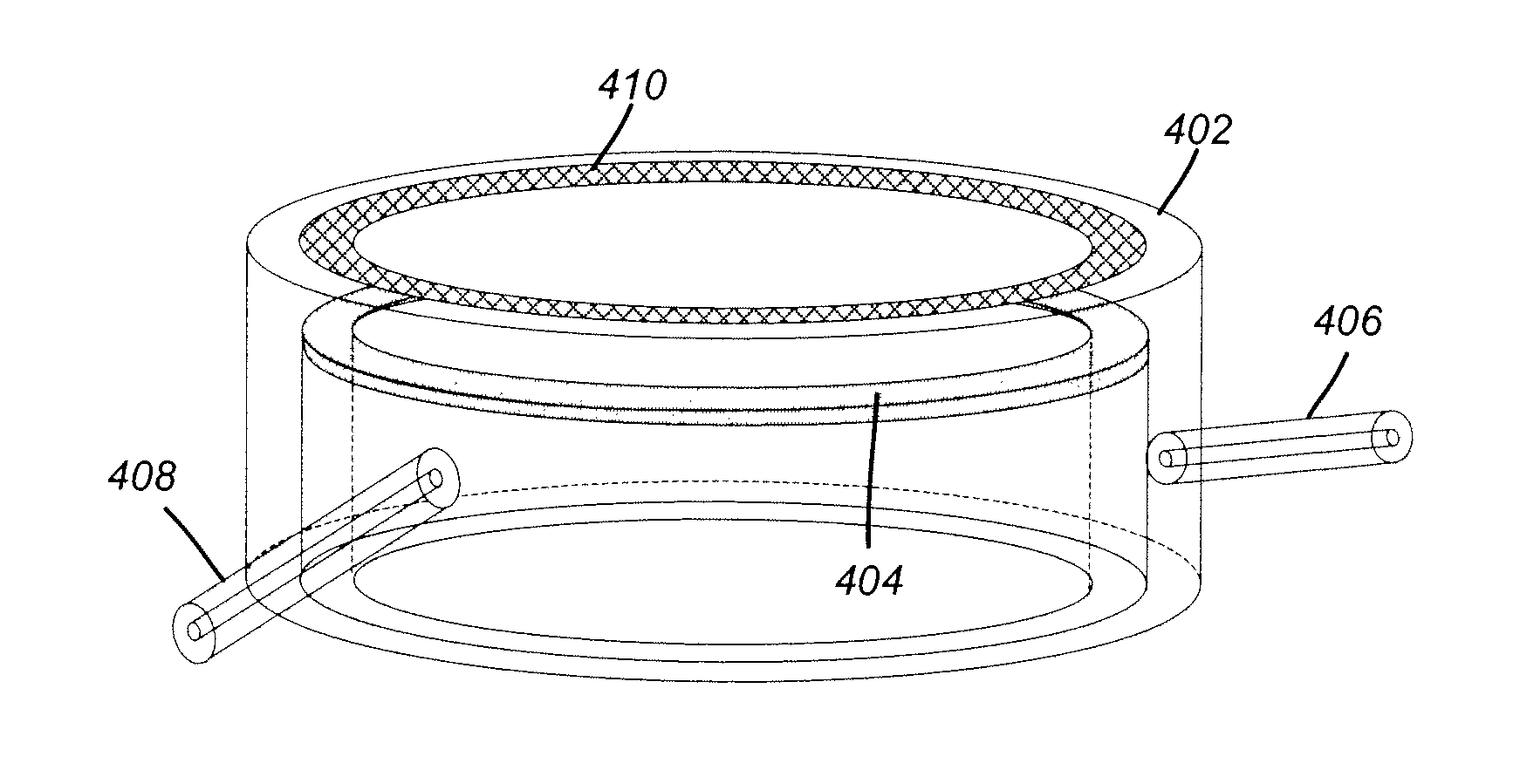
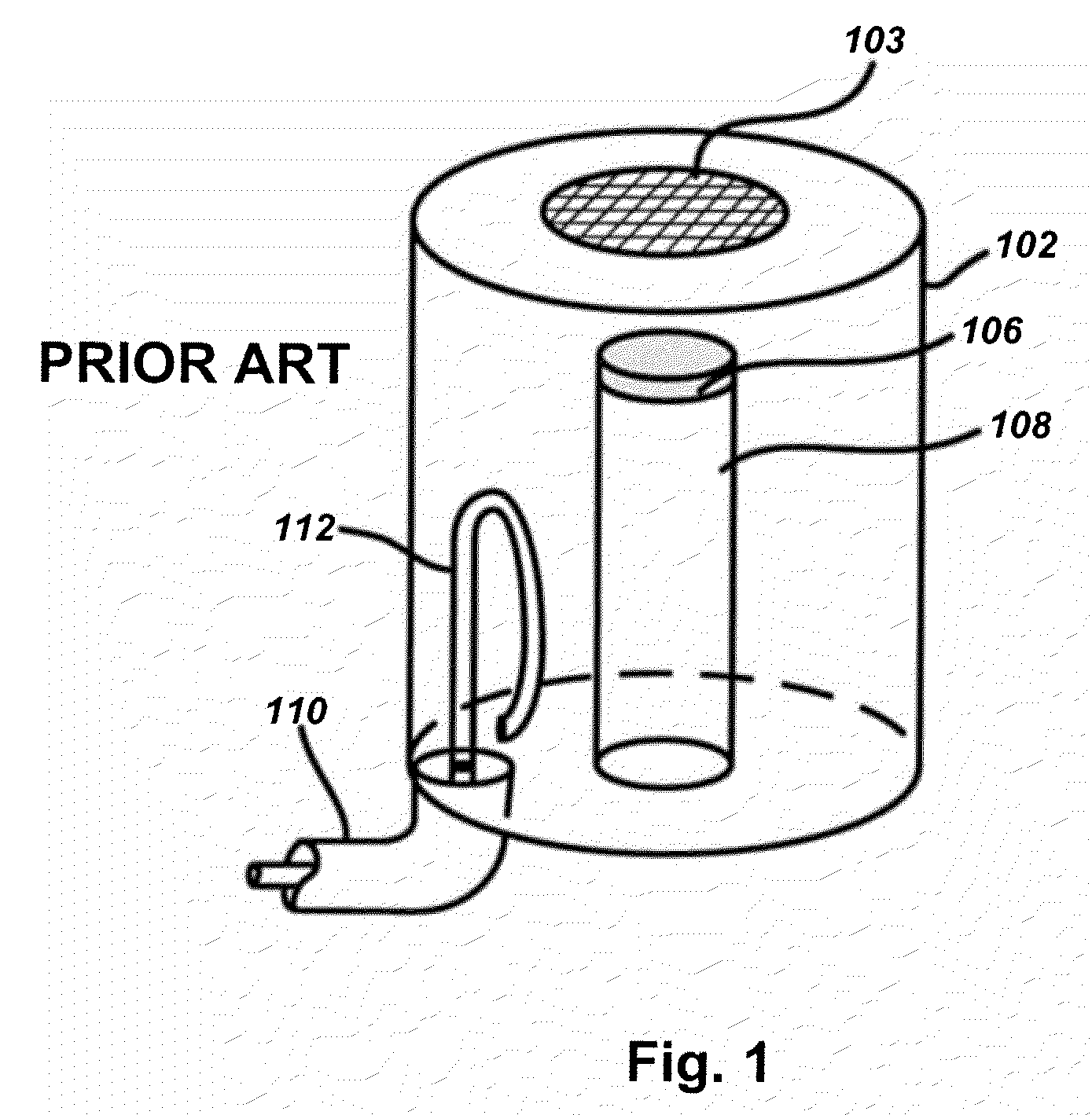
[0024]In its simplest form, an active electronically steered cathode (AESC) is similar to the input cavity of a conventional inductive output tube (IOT). FIG. 1 depicts an input cavity of an IOT, typical of the prior art. A resonant cavity 102 includes a cathode 106 atop a cathode support structure 108. A control grid 103 is positioned above the cathode 106, and a radio-frequency (RF) signal is coupled into the cavity via an RF transmission line 110 coupled to an inductive loop 112. An anode (not shown in FIG. 1) is located outside of the resonant input cavity and is biased with respect to the cathode to draw an electron beam from the cathode. The control grid 103 is positioned close to the cathode to define a G-K gap between the cathode and the control grid, and the grid is typically held at a DC potential of several hundred volts with respect to the cathode 106. This steady bias, in combination with the RF signal coupled into the G-K gap, can be used to pulse the emission of the e...


PUM


Abstract

An active electronically steered cathode (AESC) applies one or more electromagnetic modes to an input cavity, similar to that used in an inductive output tube. The structure and superposition of these modes creates local electric field maxima, causing the electron emission site or sites to move or be distributed across the surface of the cathode. Changing the amplitude, phase, or frequency of the modes provides time-variable control of the electric field profile, thereby generating electronically steered electron beams. One embodiment employs a pair of orthogonal TM modes driven out of phase, causing the electric field maximum to rotate around an annular cathode, producing a helical beam. Slots in the control grid may be used to segment the helical beam into discrete bunches to provide additional density modulation.

Description

BACKGROUND OF THE INVENTION[0001]1. Field of the Invention[0002]The present invention relates to emission-gated electron-beam devices and more particularly to devices including an active electronically steered cathode for generating one or more electron beams that are electronically steered at their points of origin.[0003]2. Description of Related Art[0004]In a conventional density-modulated device, such as an inductive output tube (IOT), radio-frequency (RF) gating of electron emission is accomplished using an input cavity structure that develops a peak electric field between the cathode surface and a control grid. By biasing the control grid with respect to the cathode, the cathode can be made to emit electrons during part of the RF cycle. As a result, the electron beam is modulated at the RF drive frequency.[0005]In some applications, it is desirable to generate a helical or deflection-modulated beam. Conventionally, such a beam is generated using bending fields that operate on t...

Claims


Application Information

Patent Timeline
IPC IPC(8): H01J29/46
CPCH01J23/04H01J25/04H01J23/09
Inventor KIRSHNER, MARK FREDERICKWILSEN, CRAIG BISSETKOWALCZYK, RICHARD DONALD
Owner L3 TECH INC
Why Eureka
Try Eureka