Electrical switching apparatus including a plurality of rogowski coils and method of calibrating the same

a technology of switching apparatus and rogowski coil, which is applied in the direction of motor/generator/converter stopper, dynamo-electric converter control, instruments, etc., can solve the problems of destroying lots of incomplete products, affecting the accuracy of the system, so as to achieve sensitive high-resistance ground fault detection and improve system accuracy

Active Publication Date: 2011-03-03
EATON INTELLIGENT POWER LIMITED
View PDF12 Cites 38 Cited by
  • Summary
  • Abstract
  • Description
  • Claims
  • Application Information

AI Technical Summary

Benefits of technology

[0017]These needs and others are met by aspects of the disclosed concept, which employ a single set of Rogowski coils for both motor protection and ground fault protect

Problems solved by technology

Further, the Rogowski coil typically is highly linear, even when subjected to large currents, such as those of low voltage and medium voltage power lines.
However, if a power system is solidly grounded, then the ground faults can be relatively very high (e.g., without limitation, thousands of amperes) and cause extensive damage to conductors, motors and other loads.
Often, users of the power system will only alarm on ground faults and plan an outage of the equipment with the ground fault rather than shutting down the process in the middle of a batch, t

Method used


Image

  • Electrical switching apparatus including a plurality of rogowski coils and method of calibrating the same
  • Electrical switching apparatus including a plurality of rogowski coils and method of calibrating the same
  • Electrical switching apparatus including a plurality of rogowski coils and method of calibrating the same

Examples


example 1

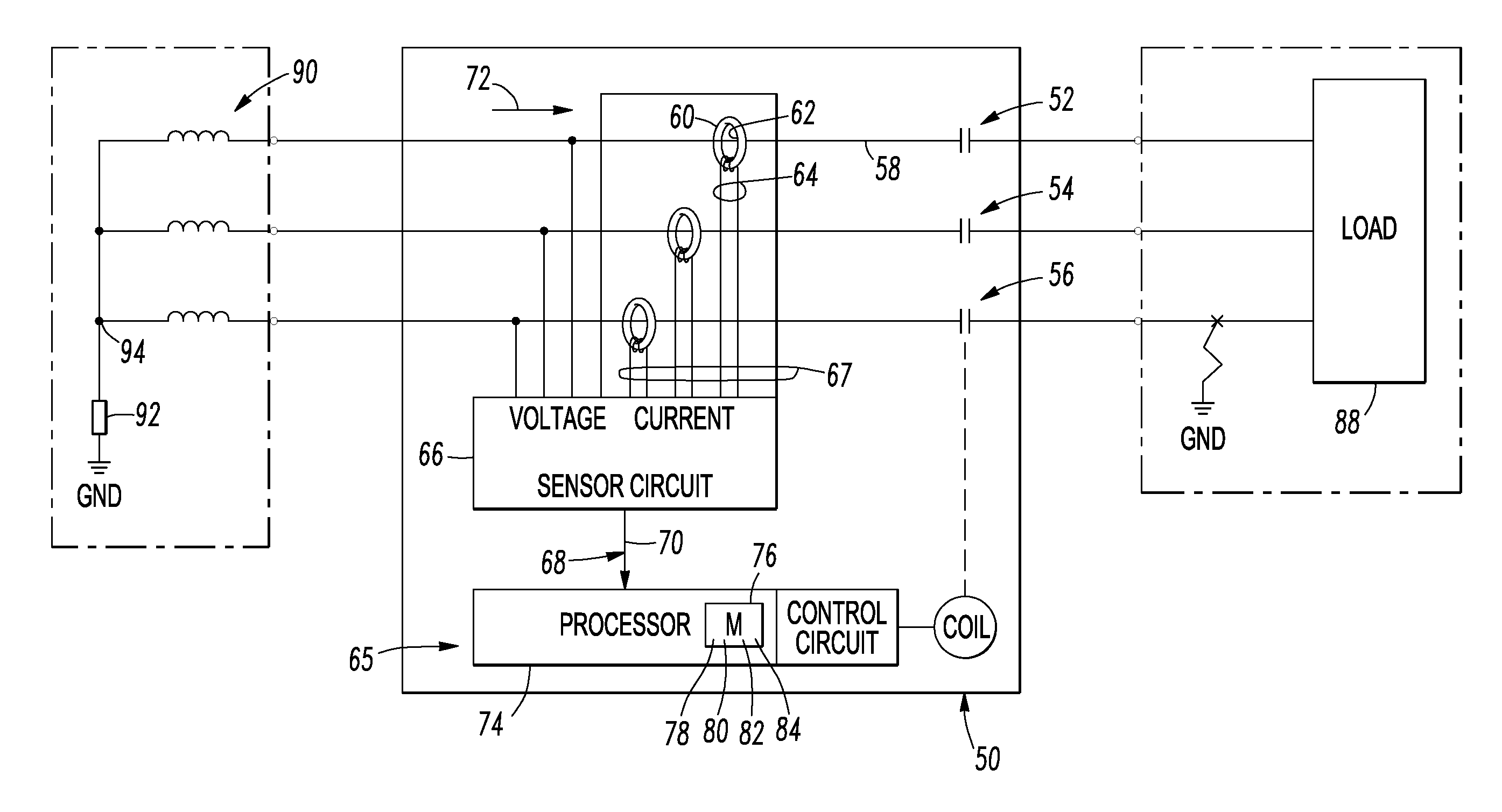
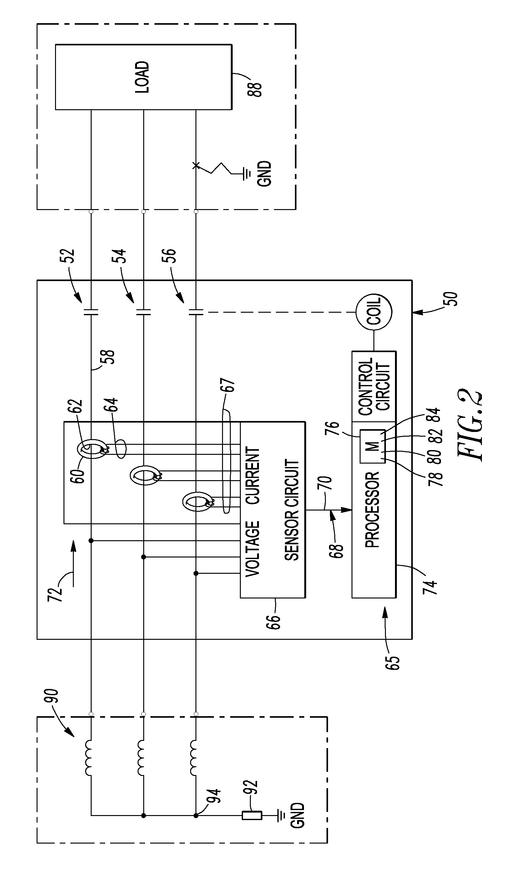
[0050]The three example Rogowski coils 60 and the sensor circuit 66 are fully calibrated to improve system accuracy and allow, for example, sensitive high resistance ground fault detection. The processor 74 of the electrical switching apparatus 50 sums the corrected value 86 of the current 72 for the three example poles 52,54,56 to determine a ground fault current value and compares that value to a predetermined value to determine if a ground fault is present. The Rogowski coils 60 eliminate of the effects of saturation of conventional current transformers and the resulting nonlinearity.

example 2

[0051]The processor 74 can cooperate with the sensor circuit 66 and the number of routines 84 to provide a first protection function (e.g., without limitation, a motor protection function for the load 88 (e.g., without limitation, a three-phase motor)) for the poles 52,54,56 as a function of the current 72 flowing through the conductor 58 of a number of the poles 52,54,56, and to provide a second ground fault protection function (e.g., without limitation, a high impedance ground fault protection function for a power system supplied by a three-phase system transformer 90 and a high resistance grounding resistor 92) as a function of the sum of the plurality of values 70. Here, the single set of Rogowski coils 60 of the three example poles 52,54,56 are advantageously used for both of the first protection function and the second ground fault protection function.

example 3

[0052]An example procedure for calibrating the electrical switching apparatus 50 will now be described. The Rogowski coil 60 includes a gain and a gain error. The corresponding sensor circuit 66 includes an offset, a gain and a gain error. For each of the three example poles 52,54,56, the example procedure determines the offset of the corresponding sensor circuit 66, determines the gain of the corresponding sensor circuit 66, determines the gain correction factor 80 for the corresponding sensor circuit 66, determines the gain of the Rogowski coil 60 by simultaneously passing the same primary current though the Rogowski coil 60 of each of the poles 52,54,56 as part of the electrical switching apparatus 50, and determines the gain correction factor 82 of the Rogowski coil 60 as a function of the determined gain of the Rogowski coil 60.


PUM


Abstract

An electrical switching apparatus includes a plurality of poles each having a Rogowski coil and a conductor passing through an opening thereof, and a processor circuit including a sensor circuit including a plurality of inputs each electrically interconnected with an output of the Rogowski coil of a corresponding pole. The sensor circuit further includes a number of outputs having values each corresponding to current flowing through the conductor, a memory including for each corresponding pole an offset value and a gain correction factor for the sensor circuit, and a gain correction factor for the Rogowski coil, a number of routines, and a processor cooperating with the sensor circuit and the routines to provide for each pole a corrected current value as a function of a corresponding one of the values, the sensor circuit offset value and gain correction factor, and the Rogowski coil gain correction factor.

Description

BACKGROUND[0001]1. Field[0002]The disclosed concept pertains generally to electrical switching apparatus and, more particularly, to such electrical switching apparatus including a plurality of Rogowski coils. The disclosed concept also pertains to methods of calibrating electrical switching apparatus including a plurality of Rogowski coils.[0003]2. Background Information[0004]A Rogowski coil is an electrical device for measuring alternating current (AC) or high speed current pulses. The Rogowski coil consists of a helical coil of wire, wound around a nonmetallic core.[0005]Another type of Rogowski coil includes first and second helical coils of wire (loops) electrically connected in series with each other. The first loop is wound with a substantially constant winding density in a first direction around a core that has a substantially constant cross section. The second loop is wound with a substantially constant winding density in a second direction around a core that has a substanti...

Claims


Application Information

Patent Timeline
IPC IPC(8): H02P1/16H02H7/08
CPCH02H1/0007H02H3/105H02H3/006
Inventor FARR, LAWRENCE B.
Owner EATON INTELLIGENT POWER LIMITED
Why Eureka
Try Eureka