Current sensor and method for manufacturing sensor module for use in current sensor

a current sensor and sensor module technology, applied in the direction of magnetic measurement, instruments, measurement devices, etc., can solve the problems of low initial strength of the magnetic field generated by the current flowing through the current path, difficult to maintain the proportional relationship between the strength of the magnetic field and the hall voltage, etc., and achieve the effect of high degree of design freedom

Inactive Publication Date: 2011-03-03
KK TOKAI RIKA DENKI SEISAKUSHO
View PDF5 Cites 58 Cited by
  • Summary
  • Abstract
  • Description
  • Claims
  • Application Information

AI Technical Summary

Benefits of technology

[0008]The present invention provides a current

Problems solved by technology

However, when the strength of the magnetic field acting on the Hall element is small, the proportional relationship of the magnetic field strength and the Hall vol

Method used


Image

  • Current sensor and method for manufacturing sensor module for use in current sensor
  • Current sensor and method for manufacturing sensor module for use in current sensor
  • Current sensor and method for manufacturing sensor module for use in current sensor

Examples


Embodiment Construction

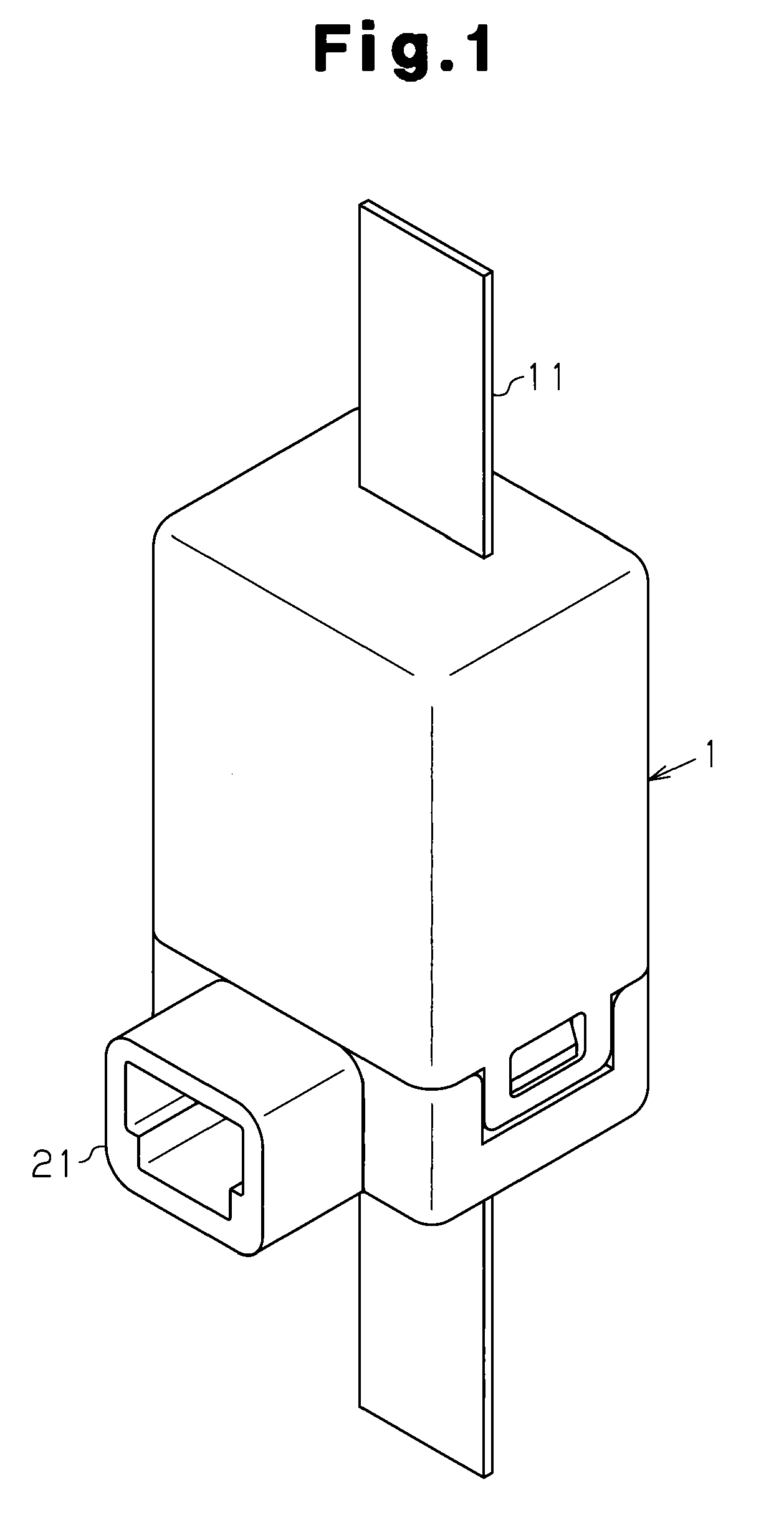
[0025]A current sensor according to a first embodiment of the present invention will now be discussed with reference to FIGS. 1 to 6. First, the structure of the current sensor will be described with reference to FIGS. 1 to 3.

[0026]As shown in FIG. 1, a case 1 covers electronic components of the current sensor. The case 1 protects the electronic components from the ambient environment. A connector 21 is arranged on the front of the case 1. The connector 21 is connected to a harness or the like (not shown) and may be used to supply the current sensor with power and output a detection signal of the current sensor to an external device. A long planar bus bar 11 is attached to the case 1 in a state extending vertically through the case 1 as viewed in the drawing. The bus bar 11 is a conductor and connected to, for example, a vehicle battery to supply an in-vehicle device with power.

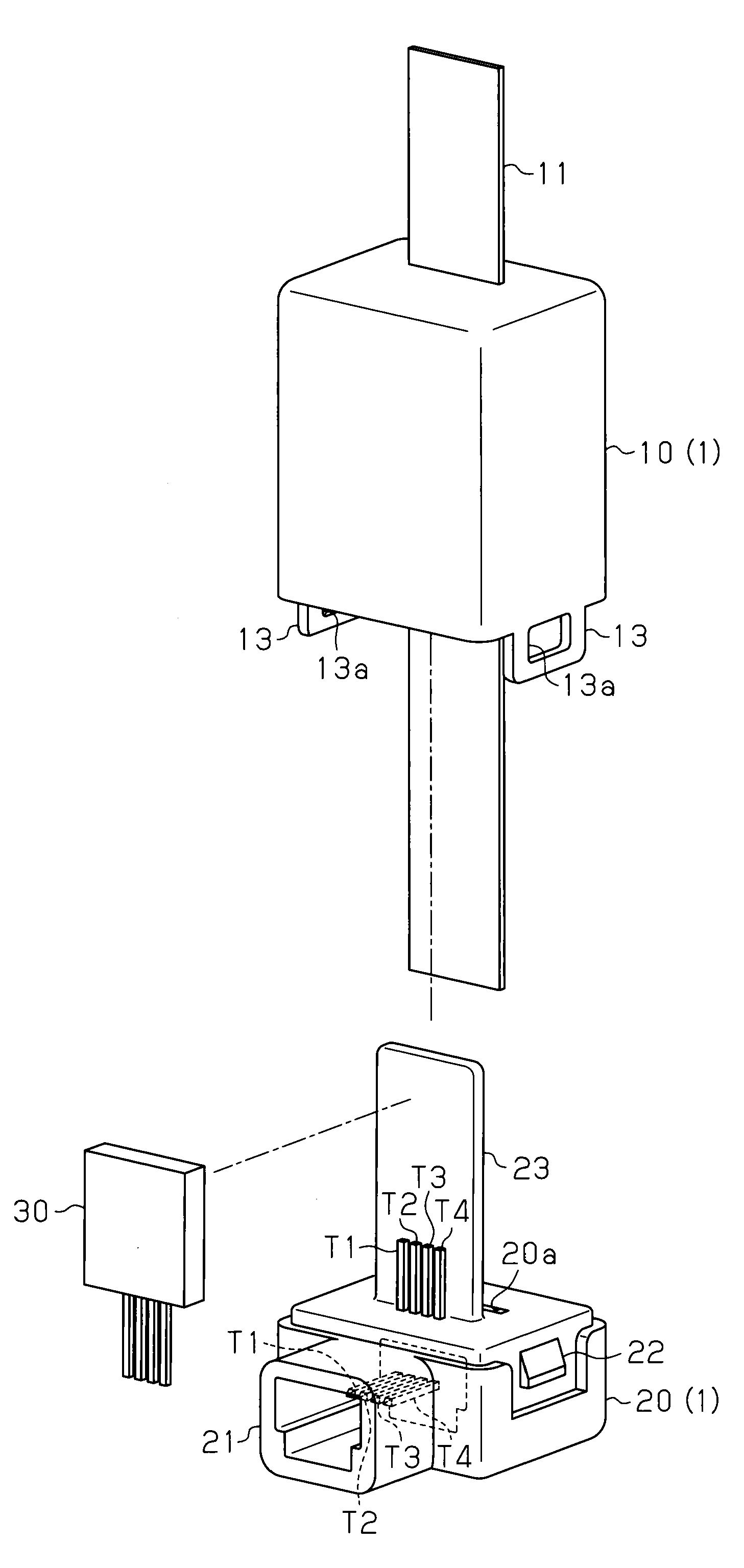
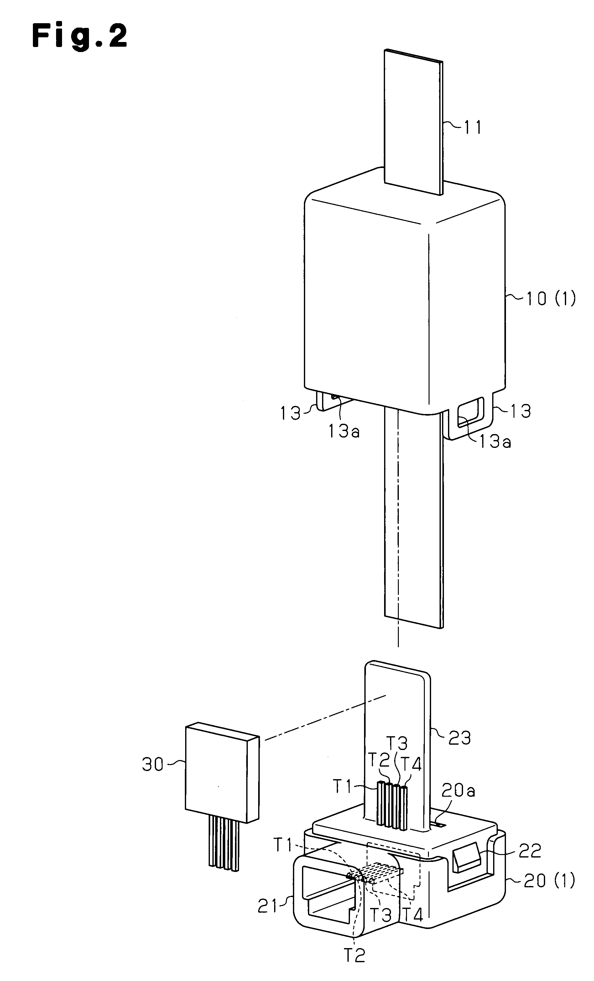
[0027]As shown in FIG. 2, the case 1 includes an upper case 10 and a lower case 20. The bus bar 11 is atta...


PUM


Abstract

A current sensor for outputting a detection signal corresponding to a current flowing through a bus bar. The current sensor includes a magnetic core that concentrates and amplifies magnetic flux generated by the current near a detection portion of the bus bar. A magnetic detection element detects the magnetic flux concentrated by the magnetic core and outputs an electrical signal corresponding to the detected magnetic flux. A signal processing circuit includes electronic components and processes the electrical signal output from the magnetic detection element to generate the detection signal. A lead frame holds the magnetic detection element and the electronic components. The magnetic detection element, electronic components, and lead frame are combined to form a single sensor module. The current sensor detects the current flowing through the bus bar with the sensor module and outputs the detection signal.

Description

CROSS-REFERENCE TO RELATED APPLICATIONS[0001]This application is based upon and claims the benefit of priority from prior Japanese Patent Application No. 2009-201717, filed on Sep. 1, 2009, the entire contents of which are incorporated herein by reference.BACKGROUND OF THE INVENTION[0002]The present invention relates to a current sensor for detecting the magnitude of current flowing through a conductor.[0003]A known current sensor uses magnetic detection elements such as Hall elements or magnetoresistance effect elements. The current detection performed by a current sensor that uses Hall elements will now be described.[0004]When current flows through a current path such as a wire, the current forms a magnetic field near the current path. The strength of the magnetic field is proportional to the magnitude of the current. When a Hall element is arranged in the magnetic field formed near the current path, the Hall element generates a Hall voltage that is proportional to the current flo...

Claims


Application Information

Patent Timeline
IPC IPC(8): G01R33/04
CPCG01R15/207G01R15/202
Inventor UENO, HIROSHIINAGAKI, YUJI
Owner KK TOKAI RIKA DENKI SEISAKUSHO
Why Eureka
Try Eureka