Al technical title is built by PatSnap Al team. It summarizes the technical point description of the patent document.
a thermal bend actuator and crack-resistant technology, applied in printing and other directions, can solve problems such as cracking and problems
Active Publication Date: 2011-03-03
SILVERBROOK RES PTY LTD
View PDF6 Cites 26 Cited by
Summary
Abstract
Description
Claims
Application Information
AI Technical Summary
This helps you quickly interpret patents by identifying the three key elements:
Problems solved by technology
Method used
Benefits of technology
[0028]In addition to the advantages discussed above in respect of the first aspect, a further advantage of inkjet nozzle assemblies according to the second aspect is that the second layer of silicon nitride is an impermeable barrier to the fluid contained in the nozzle chamber. Accordingly, aqueous ions
Problems solved by technology
Cracking may be problematic in thermal bend actuators due to inevitable stresses in the active and passive beams, but
Method used
Image
Click on the blue label to locate the original text in one second.
Reading with bidirectional positioning of images and text.
Examples
Embodiment Construction
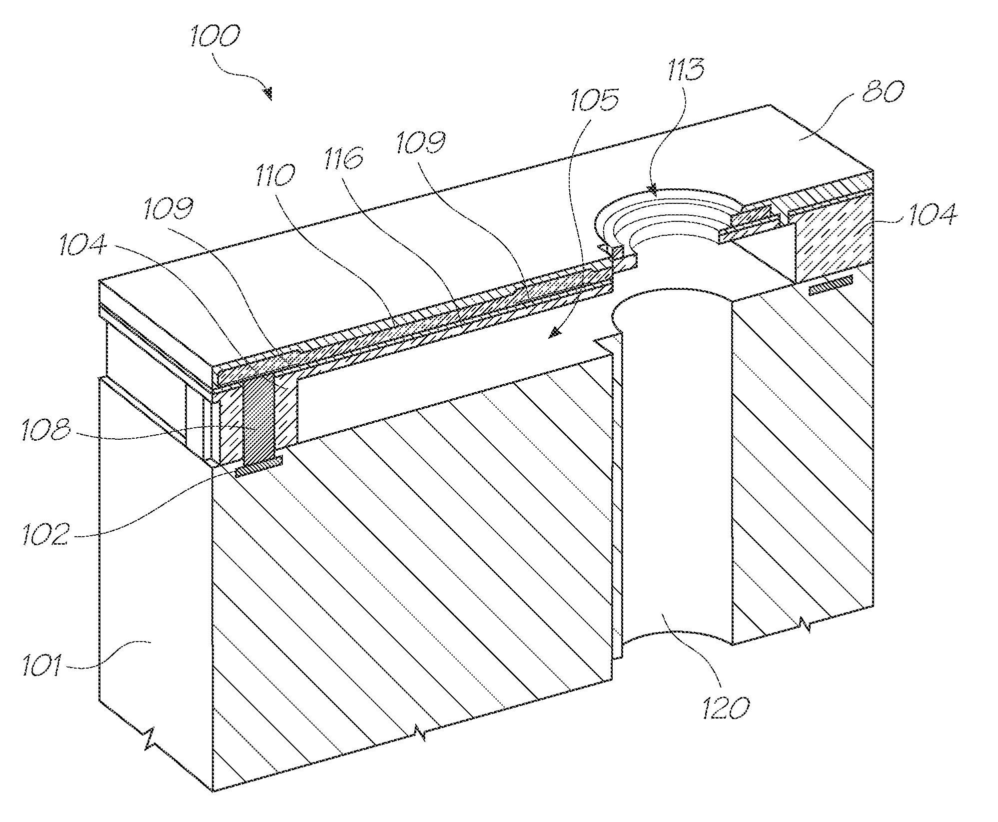
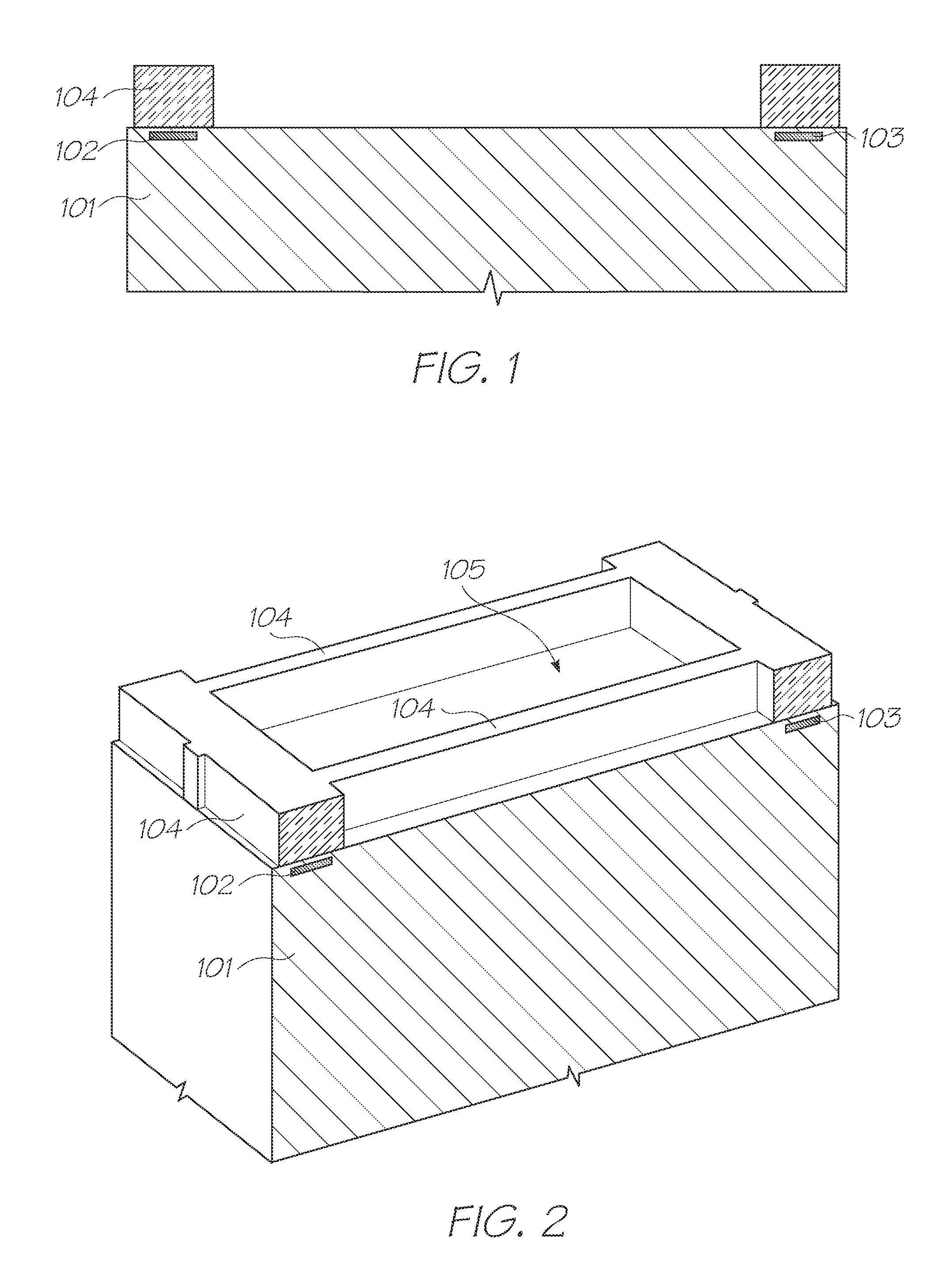
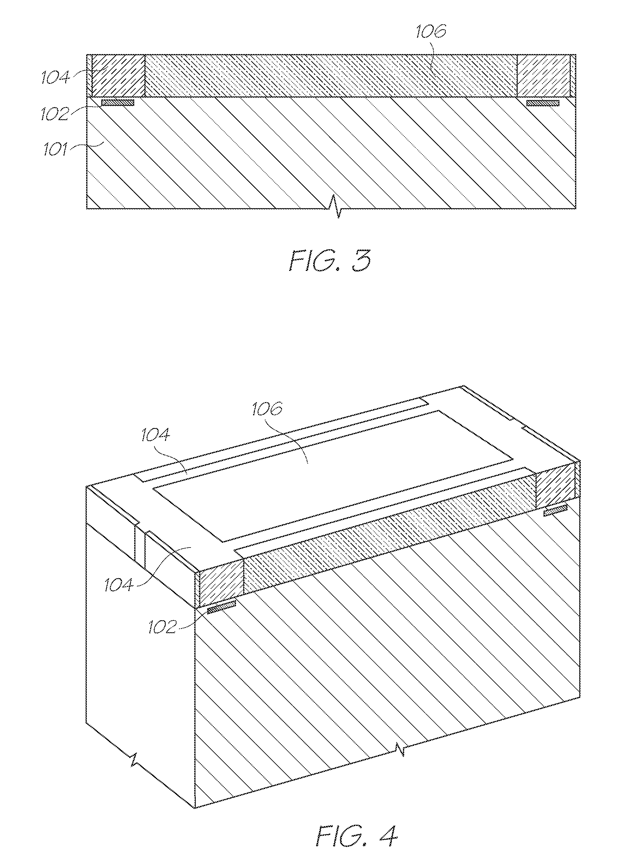
[0077]It will be appreciated that the present invention may be used in connection with any thermal bend actuator having an active beam fused to a passive beam. Such thermal bend actuators find uses in many MEMS devices, including inkjet nozzles, switches, sensors, pumps, valves etc. For example, the Applicant has demonstrated the use of thermal bend actuators in lab-on-a-chip devices as described in U.S. application Ser. No. 12 / 142,779, the contents of which are herein incorporated by reference, and a plethora of inkjet nozzles described in the cross-referenced patents and patent applications identified herein. Although MEMS thermal bend actuators find many different uses, the present invention will be described herein with reference to one of the Applicant's inkjet nozzle assemblies. However, it will, of course, be appreciated that the present invention is not limited to this particular device.
[0078]FIGS. 1 to 13 show a sequence of MEMS fabrication steps for an inkjet nozzle assemb...
PUM
Abstract
A thermal bend actuator comprises an active beam for connection to drive circuitry and a passive beam mechanically cooperating with the active beam. When a current is passed through the active beam, the active beam expands relative to the passive beam resulting in bending of the actuator. The passive beam comprises a first layer comprised of silicon nitride and a second layer comprised of silicon dioxide. The second layer is sandwiched between the first layer and the active beam to provide thermal insulation for the first layer.
Description
FIELD OF THE INVENTION [0001]The present invention relates to the field of MEMS devices and particularly inkjet printheads. It has been developed primarily to improve the robustness of thermal bend actuators, both during MEMS fabrication and during operation.CROSS REFERENCES [0002]The following patents or patent applications filed by the applicant or assignee of the present invention are hereby incorporated by cross-reference.7,416,2806,902,2556,623,1016,406,1296,505,9166,457,8096,550,8956,457,81220080129793-A120080129793-A120080129784-A120080225076-A120080225077-A120080225078-A12009013996112 / 323,47112 / 508,5642008030972812 / 114,82612 / 239,81412 / 142,779[0003]The disclosures of these co-pending applications are incorporated herein by reference.BACKGROUND OF THE INVENTION [0004]The present Applicant has described previously a plethora of MEMS inkjet nozzles using thermal bend actuation. Thermal bend actuation generally means bend movement generated by thermal expansion of one material, h...
Claims
Application Information
Patent Timeline
Application Date:The date an application was filed.
Publication Date:The date a patent or application was officially published.
First Publication Date:The earliest publication date of a patent with the same application number.
Issue Date:Publication date of the patent grant document.
PCT Entry Date:The Entry date of PCT National Phase.
Estimated Expiry Date:The statutory expiry date of a patent right according to the Patent Law, and it is the longest term of protection that the patent right can achieve without the termination of the patent right due to other reasons(Term extension factor has been taken into account ).
Invalid Date:Actual expiry date is based on effective date or publication date of legal transaction data of invalid patent.
IPC IPC(8): B41J2/05
CPCB41J2/14427B41J2/1648B41J2/164B41J2/1639
Inventor MCAVOY, GREGORY JOHNLAWLOR, VINCENT PATRICKO'REILLY, RONAN PADRAIG SEAN