LED assembly

a technology of led assembly and led components, applied in the field of led modules, can solve problems such as harmful effects on the materials and components of led assembly, and achieve the effect of avoiding undesired scattering effects on the emitted light and achieving the desired optical quality

Active Publication Date: 2011-03-03
VOSSLOH SCHWABE OPTOELECTRONICS +1
View PDF5 Cites 38 Cited by
  • Summary
  • Abstract
  • Description
  • Claims
  • Application Information

AI Technical Summary

Benefits of technology

[0007]The cover can also be designed to function as an optically-active element, for example, either as a lens, a diffusion lens to achieve light scattering or as a luminescence carrier or the like. The cover may be made from plastics such as Polymethyl Methacrylate, Polyurethane, Polycarbonate or others. The use of these plastics may result in the creation of a hermetic seal such that the entry of air and moisture into the interior space in which the LED component is positioned, or the emergence of gases from that encapsulated interior space is retarded or otherwise prevented.
[0008]The LED module preferably includes a vent device used to vent or otherwise release any harmful or performance limiting gases which may originate from the LED component and are captured within the interior space of the assembly by the cover / cover assembly. Those gases may, for example, emanate from solder contacts or flux residues present from the manufacture of the LED assembly, or otherwise be emitted by the LED into the interior space enclosed by the cover. The vent device is sized and shaped to prevent harmful gases accumulating within the interior space and being held therein which could otherwise lead to the fogging of the primary and / or secondary optics of the LED assembly, as described above. Moreover, these gases even if not directly harmful to the other materials and components within the interior space under the cover may increase the local atmospheric pressure within the covered space which in turn may result in harmful effects on the materials and components of the LED assembly.
[0009]Accordingly, the vent device is adapted to prevent harmful gases from accumulating within the interior space formed by the cover and attacking the silicone or other materials used to manufacture the LED component with a resultant fogging or discoloration of the cover and / or optics. The transparency of the primary lens or optic is thus not only maintained by this vent's presence, but will also retain its desired optical quality as well as avoiding any undesired scattering effects on the emitted light.
[0011]The vent device preferably comprises at least one channel extended through the cover. This channel may be closed by an appropriate material which will be partially permeable. A silicone material, preferably an optical silicone, may be used in the vent device to seal the cover and prevent the passage of contaminants into the LED assembly. In a preferred embodiment, the refractive index of this optical silicone is adjusted to match the refractive index of the rest of the cover, so that the silicone-closed channel remains optically invisible and can therefore be positioned within the light path of the assembly if so desired.

Problems solved by technology

Moreover, these gases even if not directly harmful to the other materials and components within the interior space under the cover may increase the local atmospheric pressure within the covered space which in turn may result in harmful effects on the materials and components of the LED assembly.

Method used


Image

  • LED assembly
  • LED assembly
  • LED assembly

Examples


Embodiment Construction

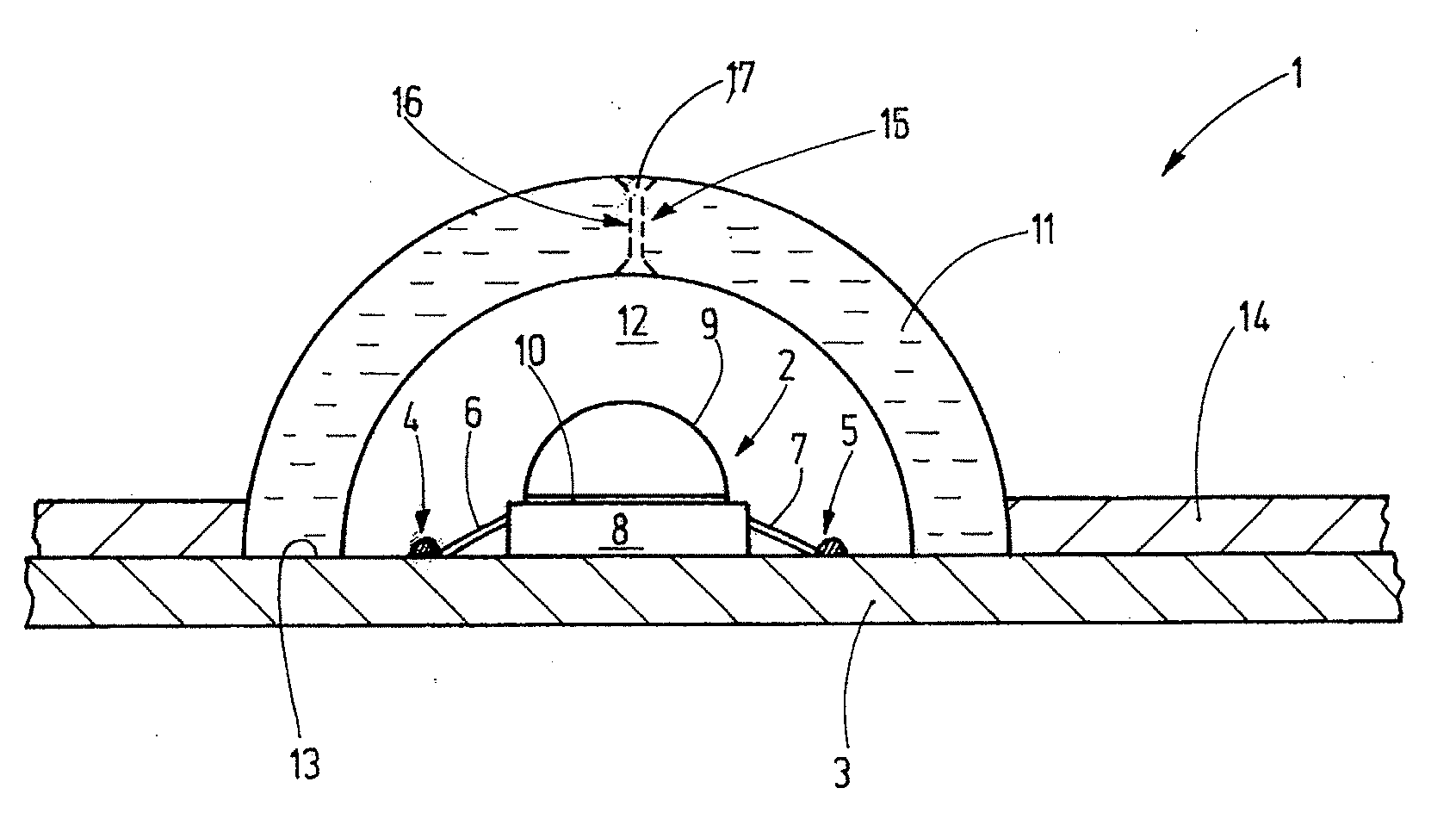
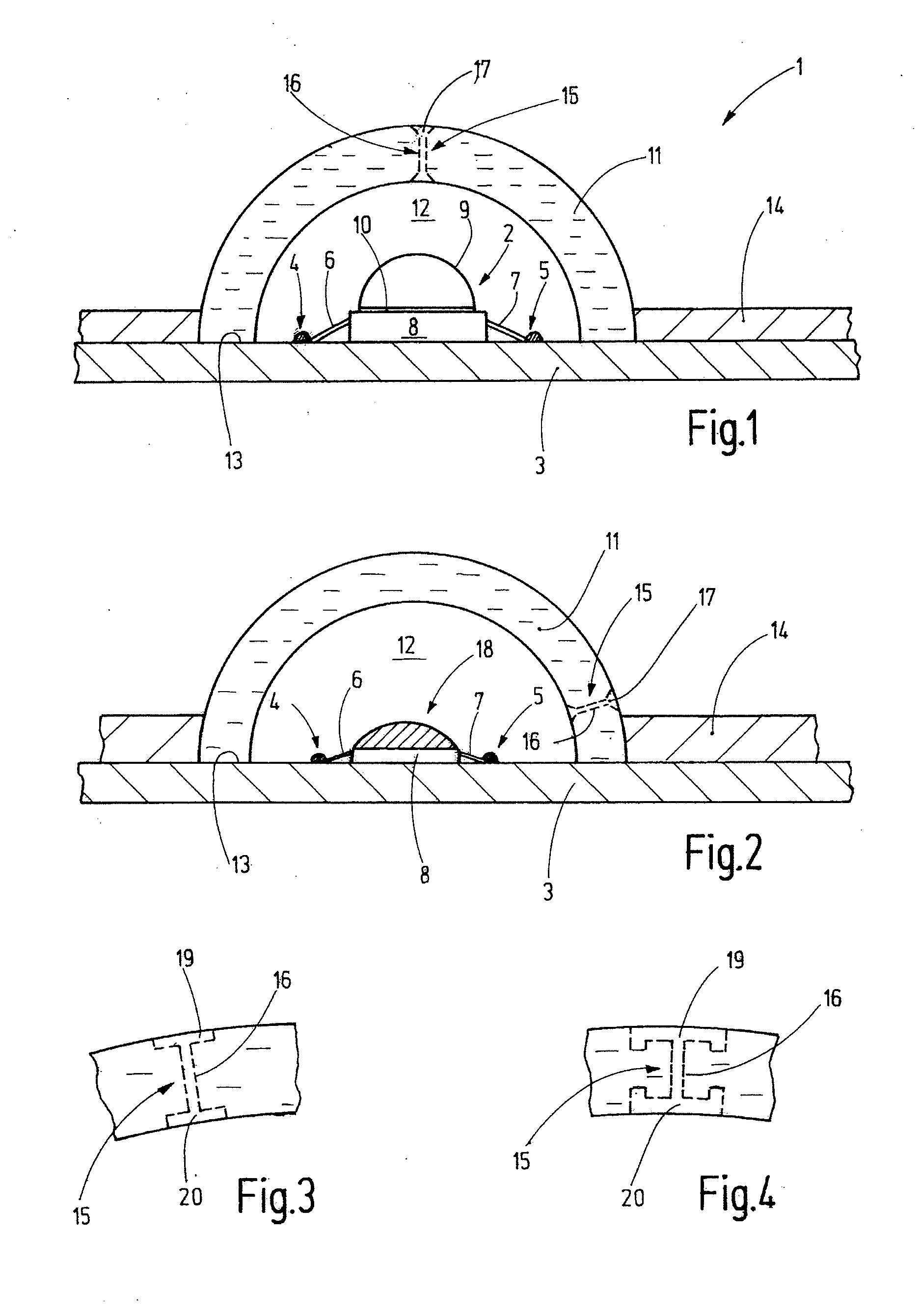
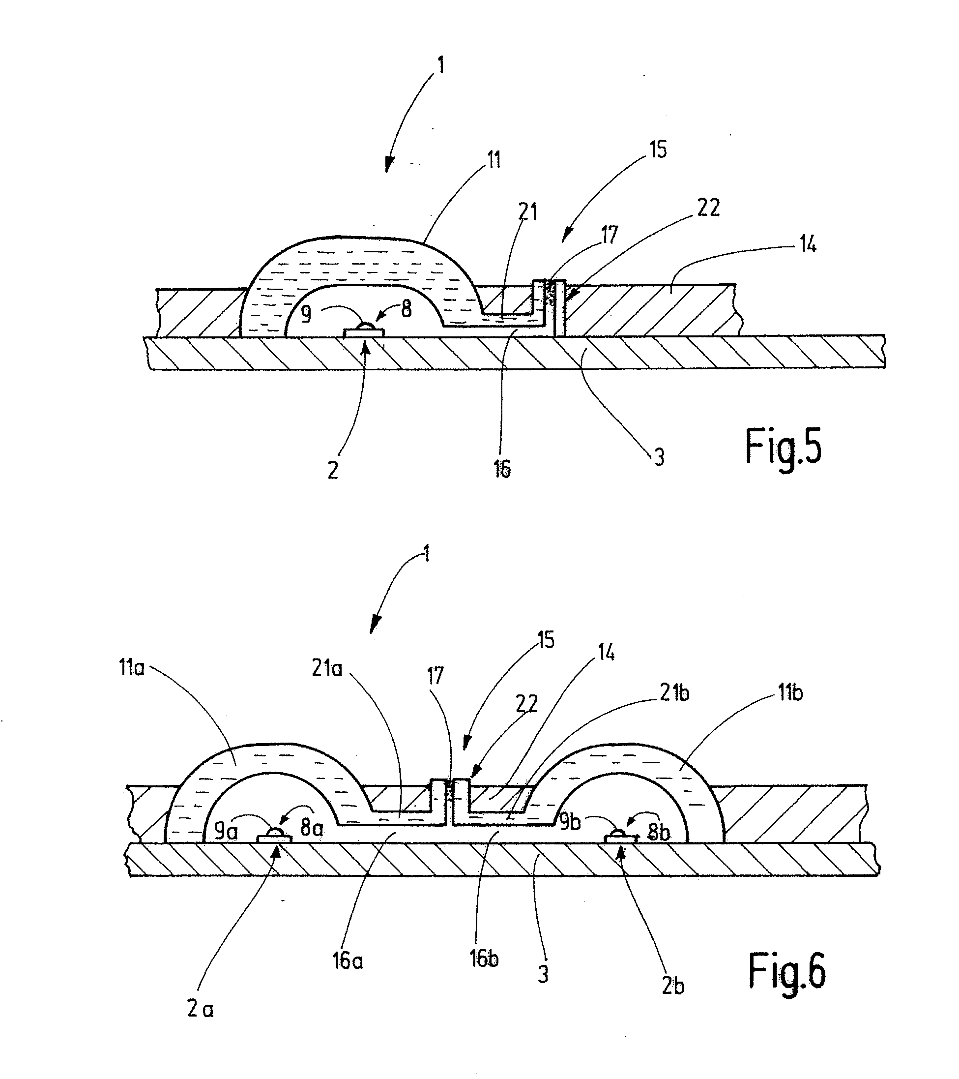
[0021]Referring now in detail to the drawings, in which like reference numerals indicate similar parts throughout the views, preferred embodiments of the assembly and the novel vent devices of our invention are disclosed in FIGS. 1 through 6.

[0022]Referring now to FIG. 1, an LED module assembly 1 is shown in a partial cross-section, it being understood by those skilled in the art that the LED module assembly may be as long and as wide, with as many LEDs positioned thereon, as desired. It is anticipated, therefore, that the LED module assembly of FIG. 1 will have at least one, but may also have several, LED components 2. The LED component is arranged on a preferably flat, plate-like support 3, which serves, for example, as a heat spreader for heat removal away from the LED components. The support 3 can also be provided, on the side facing the LED component, with leads or traces that allow power supply to the LED component. A plurality of soldering sites 4, 5 connect the connection pi...


PUM


Abstract

An LED module or assembly is disclosed, the assembly having at least one LED component mounted on a support or circuit board and an optical element which encloses the at least one LED component and defines an interior space in which the at least one LED component is housed. A vent device is defined within the optical element for permitting gases generated from operation of the at least one LED component to be vented to atmosphere. The vent device prevents outside moisture from entering the interior space, but permits the gases to pass out to atmosphere for minimizing the likelihood of fogging of the optical elements in the interior space of the assembly.

Description

FIELD OF THE INVENTION[0001]The invention relates to an LED module used for general illumination purposes.BACKGROUND OF THE INVENTION[0002]As known to those skilled in the art, LED modules used for illumination purposes, including general indoor as well as outdoor illumination, generally have a support structure, for example a circuit board with associated heat sink and mounting materials on which several LED components may be positioned, to include the chips, dies and optics, both primary and secondary, of the LED assembly. In order to protect the LED components from ambient environmental conditions in outdoor applications, the LED components are typically covered with optically transparent elements, which elements may also comprise the optics of the LED module.[0003]It is desirable to ensure that the elements covering the LEDs are not adversely affected in their optical properties by either the high heat that results from LED operation or by other external influences, and of parti...

Claims


Application Information

Patent Timeline
Patent Type & Authority Applications(United States)
IPC IPC(8): F21V29/00
CPCF21K9/00F21V3/02F21V29/506F21Y2101/02F21V31/03F21S45/30F21Y2115/10
Inventor HAND, MARK ANTHONYSEKOWSKI, DANIELBACHL, BERNHARDCLADDERS, OLAFKWETKAT, STEFAN
Owner VOSSLOH SCHWABE OPTOELECTRONICS
Why Eureka
Try Eureka