Vehicle light

a technology for vehicles and light bulbs, applied in fixed installations, lighting and heating apparatus, lighting support devices, etc., can solve the problems of not being designed to take such optical axis adjustment, unable to facilitate replacement operation, etc., to achieve effective cooling effect, facilitate replacement of axial fan motors, and effective cooling

Inactive Publication Date: 2011-03-03
STANLEY ELECTRIC CO LTD
View PDF10 Cites 57 Cited by
  • Summary
  • Abstract
  • Description
  • Claims
  • Application Information

AI Technical Summary

Benefits of technology

[0015]In the vehicle light configured as described above, the cover member can include a control circuit configured to control the LED light source unit. In this case, a compact vehicle light can be provided.
[0016]In the vehicle light configured as described above, the opening for use in replacing an axial fan motor can be provided in a bottom area of the housing, and the axial fan motor can be attached to the cover member so that the axial fan motor creates an upward air flow from below the duct. Alternatively, the axial fan motor can be attached to the cover member so that the axial fan motor creates a horizontal air flow from below the duct. In this case, the back plate can have an extension from a lower end thereof, and the extension can be configured to change the horizontal air flow to a vertical air flow passing through the duct. In these cases, the replacement of the axial fan motor can be facilitated while an effective cooling effect can be attained.
[0017]In another exemplary embodiment of a vehicle light configured according to an aspect of the disclosed subject matter, the back plate can have an extension from a lower end thereof, the opening for use in replacing an axial fan motor can be provided in a bottom area of the housing, and the axial fan motor can be attached to the extension of the back plate near the opening so that the axial fan motor creates an upward air flow passing through the duct. In this case, a more effective cooling effect can be attained.
[0018]In still another exemplary embodiment of a vehicle light configured in accordance with an aspect of the disclosed subject matter, the opening for use in replacing an axial fan motor can be provided in a top area of the housing, and the axial fan motor can be attached to the cover member so that the axial fan motor creates a horizontal air flow for sucking air from within the duct. In this case, the replacement of the axial fan motor can be facilitated while an effective cooling effect can be attained.
[0019]In any of the vehicle lights configured as described above, the heat conduction member may be a heat pipe. In this case, the heat conduction from the LED light source unit to the heat sink can be reliably achieved.
[0020]As described above, a vehicle light made in accordance with principles of the presently disclosed subject matter and as shown by the above various exemplary embodiments can facilitate the replacement operation of an axial fan motor (or other exhaust device) and can facilitate optical axis adjustment of an LED light source unit, and can simultaneously promote dissipation of heat generated by the powered LED light source unit.

Problems solved by technology

Accordingly, even if there is a need to replace the blower fan 250 with a new one when the blower fan 250 has been damaged, the replacement operation cannot be done with ease due to the sealed structure(s).
However, the structure of the headlight 200 is not designed to take such optical axis adjustment into consideration.

Method used


Image

  • Vehicle light
  • Vehicle light
  • Vehicle light

Examples


Embodiment Construction

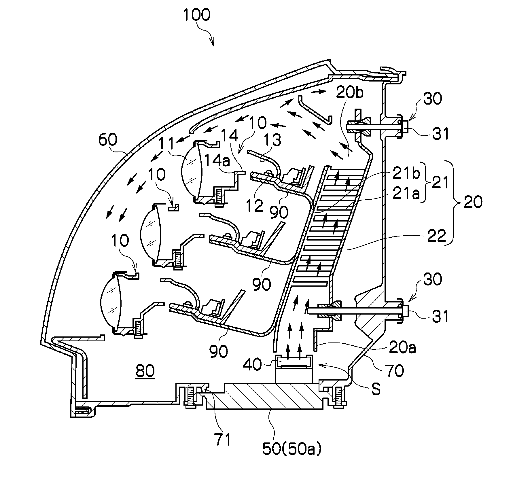
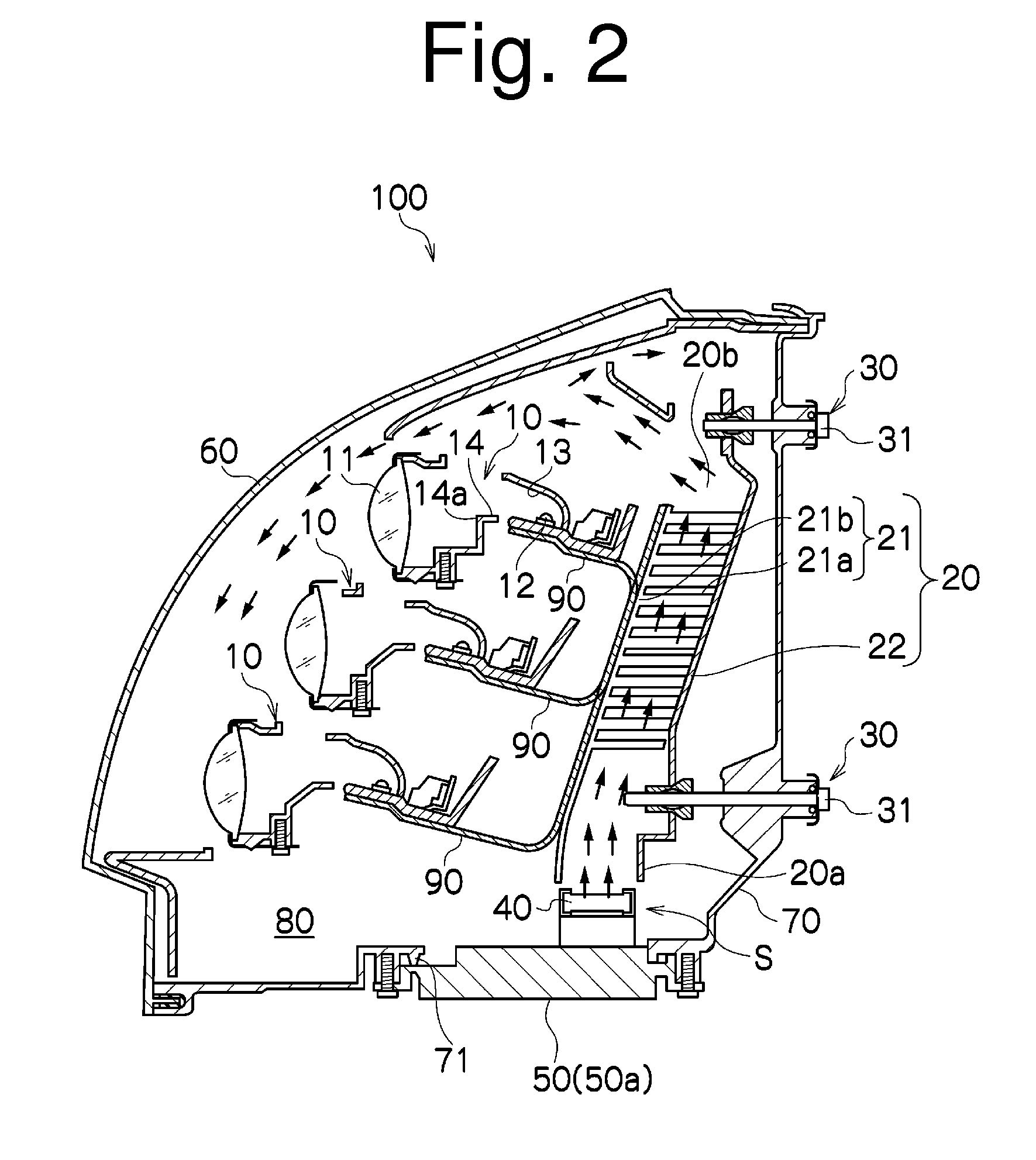
[0028]A description will now be made below to vehicle lights according to one aspect of the presently disclosed subject matter with reference to the accompanying drawings in accordance with exemplary embodiments.

[0029]The vehicle light 100 of the exemplary embodiment of FIG. 2 can be configured as a vehicle headlight such as a headlight for an automobile. As shown in FIG. 2, the vehicle light 100 can include at least one LED light source unit 10 (three LED light source units 10 are exemplified in FIG. 2), a duct 20, an optical axis adjusting mechanism 30, an axial fan motor 40, a cover member 50, and the like.

[0030]Furthermore, the vehicle light 100 can include a lens cover 60 and a housing 70 which constitutes a light chamber 80 together with the lens cover 60. The LED light source units 10 can be disposed within the light chamber 80 in the vertical direction, as shown in FIG. 2.

[0031]Each of the LED light source units 10 can include a projection lens 11 disposed in the forward dir...


PUM


Abstract

A vehicle light is disclosed that can facilitate the replacement operation of an axial fan motor and the optical axis adjustment of an LED light source unit as well as can simultaneously promote dissipation of heat generated by the LED light source unit when powered. The vehicle light can include at least one LED light source unit disposed within a light chamber defined by a lens cover and a housing. The vehicle light can further include, within the light chamber: a heat sink including a heat sink main body to which the LED light source unit is secured and a plurality of heat dissipation fins; a back plate separated away from the heat sink main body at a certain distance, the back plate constituting a part of a duct together with the heat sink, the duct containing the plurality of heat dissipation fins between the heat sink main body and the back plate; an optical axis adjusting mechanism configured to adjust the optical axis of the LED light source unit by moving the duct; a heat conduction member configured to conduct heat generated by the LED light source unit, when turned on, to the heat sink; an axial fan motor configured to generate an air flow passing through the duct to circulate the air flow within the light chamber; and a cover member, the housing having an opening used for replacing the axial fan motor with another one, the cover member being detatchably attached to the housing so as to cover the opening of the housing. The axial fan motor is disposed near the opening at a position where the axial fan motor does not interfere with the duct moved by the optical adjusting mechanism.

Description

[0001]This application claims the priority benefit under 35 U.S.C. §119 of Japanese Patent Application No. 2009-194168 filed on Aug. 25, 2009, which is hereby incorporated in its entirety by reference.TECHNICAL FIELD[0002]The presently disclosed subject matter relates to a vehicle light, and in particular, to a vehicle light that can facilitate the replacement operation of an axial fan motor and the optical axis adjustment of an LED light source unit as well as can simultaneously promote dissipation of heat generated by the powered LED light source unit.BACKGROUND ART[0003]Conventional known vehicle lights can include a lens cover, a housing, and at least one LED light source unit disposed in a lighting chamber defined by the lens cover and the housing. One example thereof is disclosed in Japanese Patent No. 4270153.[0004]FIG. 1 shows a vehicle light 200, as disclosed in Japanese Patent No. 4270153. The vehicle light 200 can include three LED light source units 210, heat conduction ...

Claims


Application Information

Patent Timeline
Patent Type & Authority Applications(United States)
IPC IPC(8): F21V29/02B60Q1/00
CPCB60Q1/007F21S48/1159F21S48/325F21V29/76F21V29/02F21V29/745F21S48/335F21S41/147F21S45/435F21S45/49F21S45/60F21V29/67
Inventor NAGASAWA, SATOSHIMATSUNO, TAKASHIYAMAHANA, CHIKAKO
Owner STANLEY ELECTRIC CO LTD
Why Eureka
Try Eureka