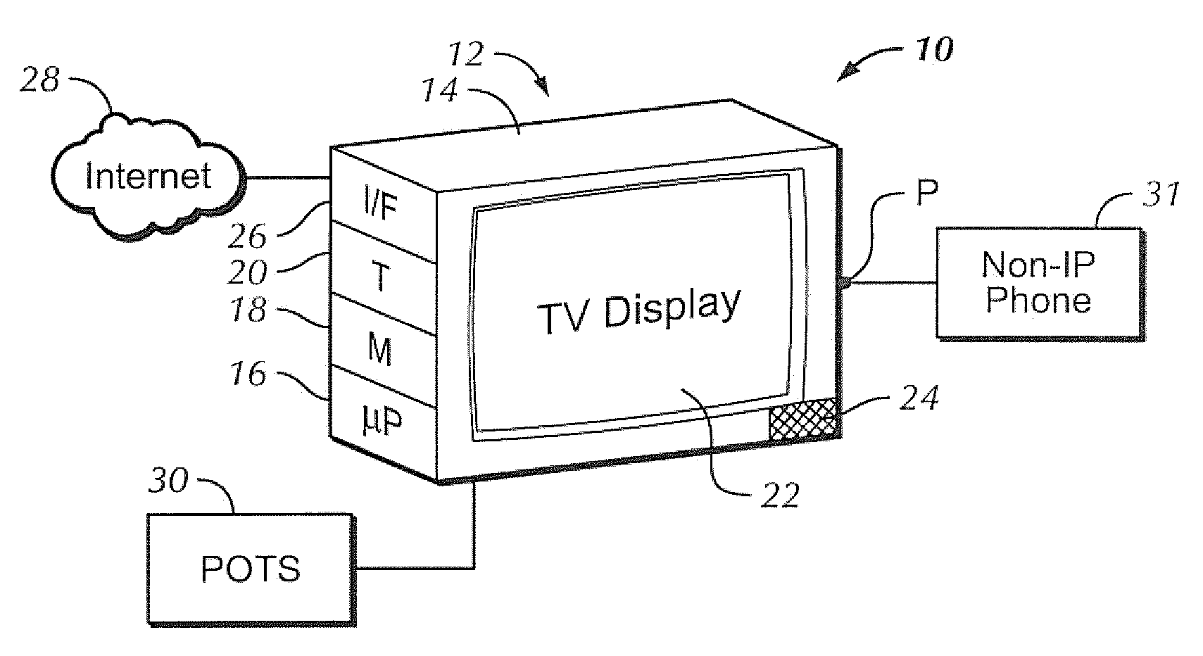
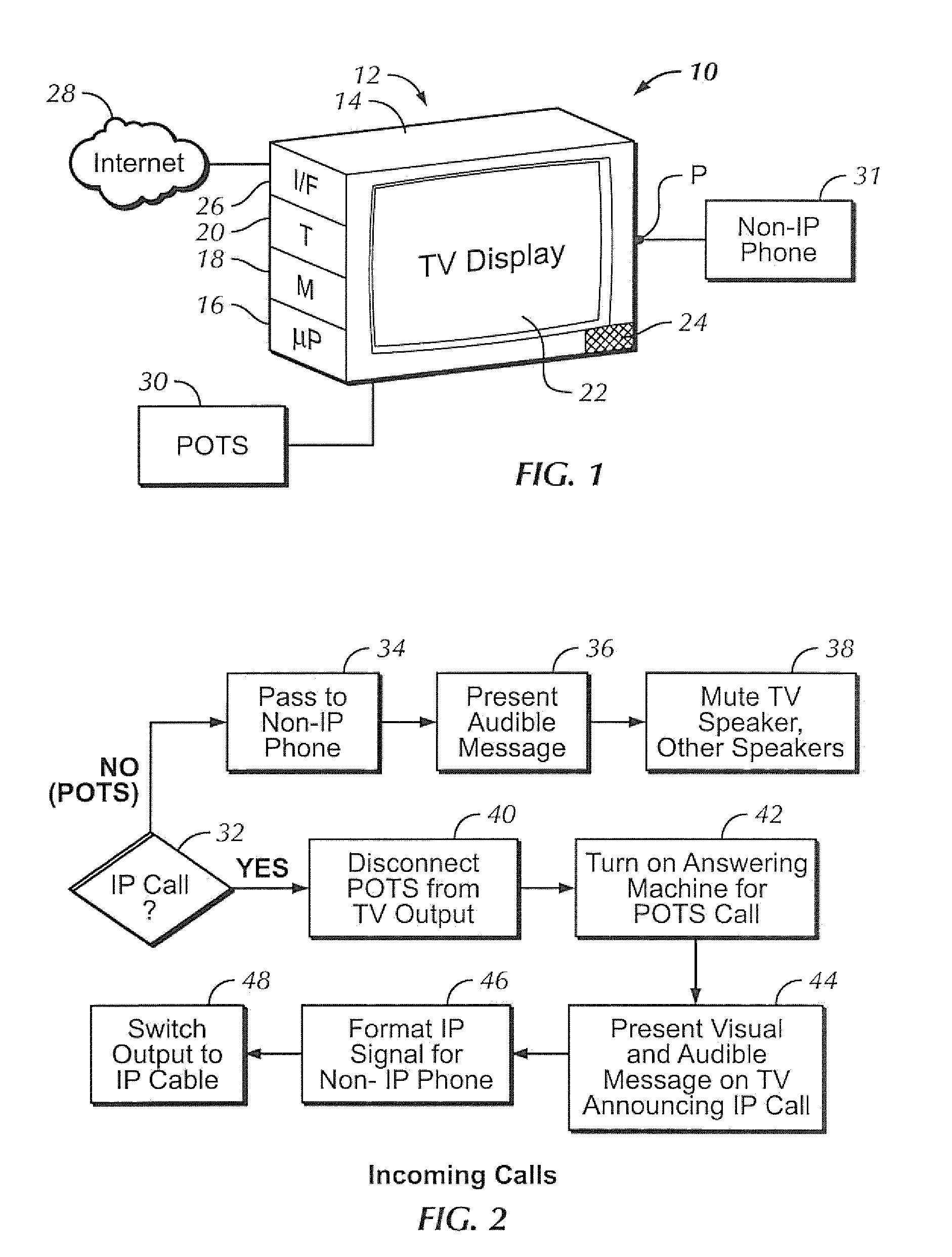
[0017]Referring initially to FIG. 1, a system 10 includes a TV 12 defining a TV chassis 14 holding a TV processor 16 accessing a computer readable storage medium 18, such as solid state and/or disk-based storage. The storage medium 18 may store data and software executable by the processor 16 for undertaking all or parts of the logic divulged herein for processing telephone calls. The processor 16 typically communicates with a TV tuner 20 in the chassis 14 for presenting TV signals on a display 22 and speaker(s) 24, it being understood that one or more of the components above may alternatively be incorporated in a set-top box that is separate from the chassis 14. The TV 12 may be an analog and/or digital TV with a flat panel (matrix-type) standard definition and/or high definition (HD) display, although other types of displays may be used.
[0018]As shown in FIG. 1, the TV 12 can also include an Internet interface 26 such as but not limited to a wired or wireless modem for enabling the processor 16 to communicate with a wide area network such as the Internet 28 through which IP-based voice calls can be communicated. Without limitation the Internet interface 26 may be an Ethernet RJ45 interface or 802.11a/b/g/n interface.
[0019]Also, the TV 12 can communicate with the non-IP POTS 30, it being understood that while separate connections are shown for the POTS 30 and Internet 28, the TV 12 may communicate with both using a single input interface. The TV 12 also communicates with a non-IP conventional phone 31, typically located in the same dwelling as the TV 12, over a communication port “P” that may be, e.g., an RJ-11 terminal.
[0020]Example incoming call logic may be seen in reference to FIG. 2. The TV 12 can be programmed in the factory with voice over IP capability including an IP phone number which may be called by outside callers, it being understood that the IP phone number in some embodiments may not programmed into the TV until after purchase and IP registration. Specifically, purchase of the TV, the user activates an IP phone service in accordance with IP phone registration policies and procedures known in the art. Also, the POTS line in the dwelling can be connected to the TV so that the TV receives all calls into the dwelling, both IP calls and POTS calls to the non-IP phone 31.
[0021]Decision diamond 32 indicates that when the TV processor 16 detects an incoming telephone call, it determines whether the call is IP-based or a POTS call. The determination can be made by simply noting which interface the call arrives at, e.g., an Internet interface (indicating an IP call) or the POTS interface (indicating a POTS call.) Or, the determination can be made by ascertaining whether the accompanying ring tone is 90 volts AC (indicating a POTS call) and/or by determining whether the incoming call contains IP packets, indicating an IP-based call.
[0022]If the call is a POTS call the TV 12 in effect functions as a passive connection, passing the POTS call to the non-IP phone 31 at block 34 through, e.g., an RJ-11 connection. If desired, at block 36 an audible call message such as an emulated POTS ring tone can be presented on the speaker 24. Also, if desired at block 38 the TV speaker 24 subsequently can be muted for the duration of the call. The TV 12 can also send a mute signal to other home system components over a home network infrared link or CEC link. It is to be understood that similar muting may be effected for IP-based calls.
[0023]In contrast, when an IP-based call is received at decision diamond 32, the logic moves to block 40 to disconnect the POTS line from its output port P. At block 42 if desired the TV can activate an answering machine function which may be implemented in software executed by the TV processor 16 so that if a POTS call is received during the IP-based call, the call can be answered by the answering machine function executed by the TV processor 16, which may store messages on the medium 18. It is to be understood that the inverse may also be used, i.e., if a POTS call is in progress and a new IP call arrives, the IP call is sent to the answering machine function.
[0024]Proceeding to block 44, the TV processor 16 can cause the TV 12 to present a visual and/or audible message (on, respectively, the display 22/speaker 24) to announce the incoming IP-based call. The audible message may be without limitation an audible bell tone. At block 46 the IP call data is formatted as appropriate for the non-IP phone 31 and then passed through the port “P” to the phone 31 at block 48. Preferably, the logic of FIG. 2 may be implemented even when the TV/display is in a standby mode. Also, to be eco-friendly, the user could be given an option to enable IP call reception while the TV is in the standby mode, as the assumption is that to enable IP phone capability in the standby mode would require more power. Furthermore, for safety, when there is a loss of power, the POTS pass through remains operational.
[0025]It may now be appreciated that because the TV 12 has audio capability, it can easily signal to the user the presence of an incoming call. Hence there is no need for the TV to be able to create the approximately 90V AC voltage to the POTS line to ring the bell on the phone 31 during POTS calls. Instead, the TV 12 need only provide 24V˜48V DC for the local loop current to the phone 31, although the phone 31 may still receive 90 volts AC from the POTS line that the TV passes through.
[0026]With more specificity, the pass through POTS line carries the 90V AC which is merely passed by the TV to the phone, so there is no need for the TV itself to generate the 90 VAC. In the case of a DECT phone interface, the TV merely needs to send the Ling command. In the case of an incoming IP call, however, since there is no 90 VAC the TV either generates the 90 VAC ring signal or relies upon the use of an audible tone from the speakers 24 to notify the user that a call was received.
[0027]This results in the latter case in a cost savings, since there is no need to include a high voltage AC voltage source in the TV when IP phone connectivity is added.
[0028]In communicating with the non-IP phone 31 the TV 12 may use a standard such as the Digital Enhanced Cordless Telecommunications (DECT) standard to signal and then communicate and pass the IP phone call to the non-IP phone 31.
[0029]FIG. 3 illustrates example outgoing call logic for IP calls, it being understood that for POTS calls from the phone 31 the phone 31 is simply dialed conventionally and the call passes through the TV 12. At block 50, a special signal is received from the phone 31 indicating a desire to place an IP-based call. The special signal may be a DECT protocol signal or it may be a signal corresponding to user keypad input. For example, a rudimentary code may be used to allow the POTS phone user to signal to the TV via the phone line a desire to activate the IP calling feature of the TV. As a non-limiting illustration, when the user tries to make call, if no prefix is used, the TV 12 assumes a POTS call is intended, whereas if a special prefix such as “47#” is entered on the keypad of the phone 31, the TV 12 will implement IP-based calling.
[0030]Assuming an IP call is indicated, at block 52 the TV 12 can send to the phone 31 a distinct dial tone corresponding to IP calling, which is a different tone than that sent for a POTS call. In this way the user can aurally confirm the IP phone mode. The TV 12 then configures itself for an IP call at block 54 by, e.g., translating signals from the phone 31 into IP packets.
[0031]Furthermore, once in the IP phone mode, if desired at block 56 as the user enters a phone number the TV 12 can perform a search to confirm the number and name of the called party.
[0032]If the number is not found in a list of formerly dialed IP addresses (which may be stored on the medium 18) at decision diamond 58, at block 60 the user can then be prompted to enter information to identify that number and add it to the list. If recipient data becomes available during the call at block 62 via the IP phone system, the TV processor 16 can automatically add it to the list. The IP call is then placed at block 64 to the destination input on the phone 31.
[0033]In any case, it will readily be appreciated that as discussed further below the superior graphical capability of the TV 12 can be used to provide an easy to use menu and if necessary, set up menu system. For example, when an incoming call is received, as shown in FIG. 4 the TV display 22 can prompt a user to answer or not. Additional information can be presented such as caller ID on the display 22, which is much easier to view than the typical telephone display.
[0034]FIG. 5 shows that when the IP-indicating special code is entered on the phone 31 as discussed above, the TV display 22 can present a prompt to enter a number. In the example shown, “XY” has been entered as a partial entry. As a consequence, available numbers in the list of previously called numbers that begin with “XY” are presented as shown, from which the user can select if desired using, e.g., a TV remote control. Or, the user can simply complete inputting the desired number on the telephone keypad.
[0035]If desired, if a quality of service index (such as but not limited to signal to noise ratio, received signal strength, or bit error rate) of an IP-based call drops below a minimum acceptable threshold, the TV can automatically redial the dropped number over the POTS network.
[0036]While the particular TV ACTING AS POTS PHONE SWITCH is herein shown and described in detail, it is to be understood that the subject matter which is encompassed by the present invention is limited only by the claims.