Infinitely-variable, hydro-mechanical transmission using fixed displacement pumps and motors

a fixed displacement, hydro-mechanical technology, applied in the direction of fluid couplings, couplings, transportation and packaging, etc., can solve the problems of large power loss, large power loss, and inability to control the speed of the transmission path, so as to reduce the cost of batteries and electrics, handle high power and torque, and infinite variability of vehicles

Active Publication Date: 2011-03-10
LLOYDCO
View PDF2 Cites 11 Cited by
  • Summary
  • Abstract
  • Description
  • Claims
  • Application Information

AI Technical Summary

Benefits of technology

It is an object of the present invention to provide a hydro-mechanical transmission system that can be used on plug-in electric/gas hybrids vehicles to reduce the cost of the batteries and electrics.
It is an object of the present invention to provide a hydro-mechanical transmission system that can ac...

Problems solved by technology

The size, cost, complexity, noise, failure rate, and energy losses (under some conditions) of variable displacement pumps and motors are much greater than fixed displacement devices of the same max. displacement and are to the detriment of the transmission.
These re-circulating schemes result in large pow...

Method used


Image

  • Infinitely-variable, hydro-mechanical transmission using fixed displacement pumps and motors
  • Infinitely-variable, hydro-mechanical transmission using fixed displacement pumps and motors
  • Infinitely-variable, hydro-mechanical transmission using fixed displacement pumps and motors

Examples


Embodiment Construction

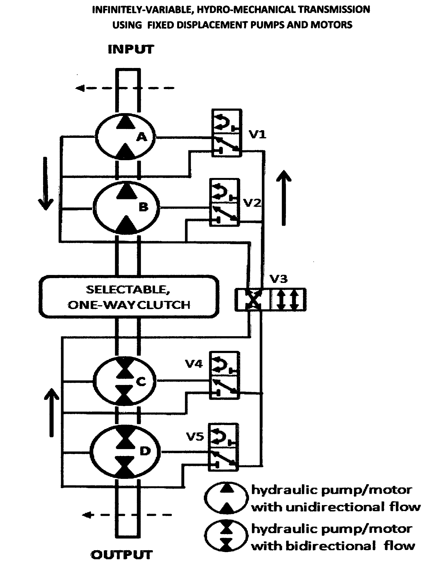
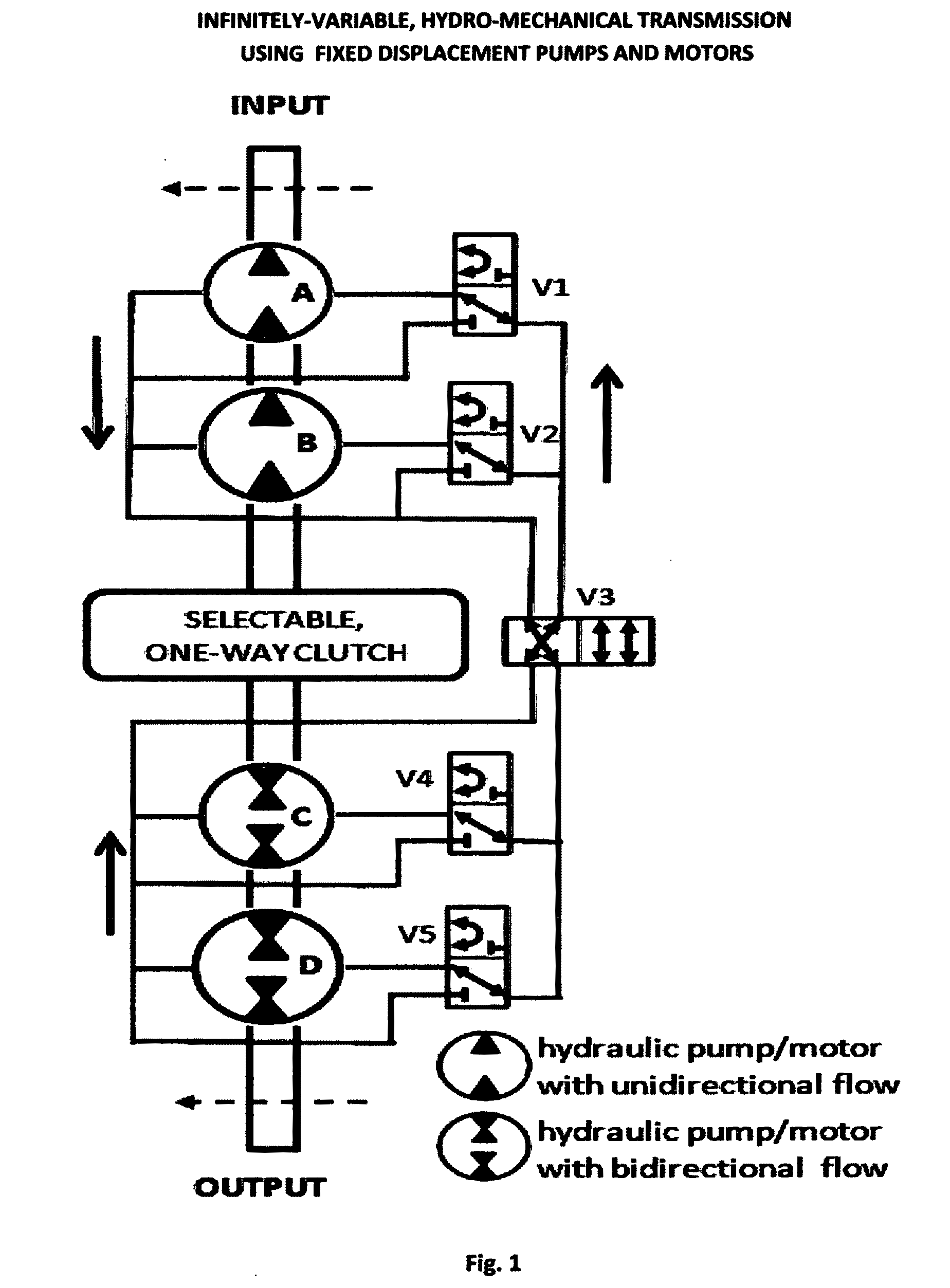
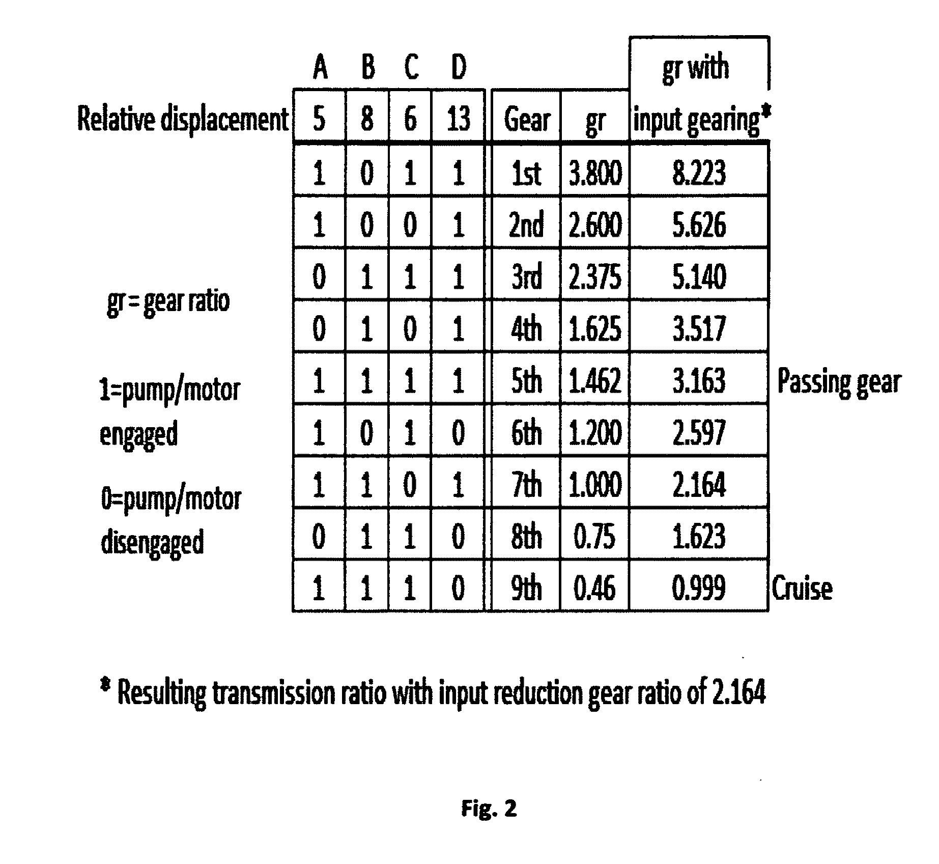
The example used to describe the basic transmission (FIG. 1) uses two hydraulic devices on the input shaft of the transmission capable of operating either as a pump or a motor and two pump / motors on the output shaft capable of operating with the fluid flow in either direction. With valves V1, V2, V4, and V5 in the position shown, both input devices A and B will pump fluid to motors C and D. The transmission ratio is the input rpm divided by the output rpm. In this case the ratio will equal the total output displacement (D+C) divided by the displacement of (A+B). If, for example, V2 is change to the position that causes the fluid to re-circulate within pump / motor B, the transmission ratio or gear ratio will become (C+D) / A. The chart in FIG. 2 shows all the combinations possible with the relative displacements shown resulting in 9 forward speeds. Changing V3 shift the transmission to reverse, and all the same speeds ranges will result.

It is desirable to have an input speed reduction g...


PUM


Abstract

This invention consists of two or more fixed displacement hydraulic pump/motors mounted on a common input shaft hydraulically connected to two or more fixed hydraulic pump/motors mounted on a common output shaft. The relative displacements of the pump/motors are chosen such that by selectively activating the individual pump/motors, the transmission ratio can be changed in the case when the input devices and acting as pumps driving the output devices as motors (conversely when driving the vehicle in reverse). Further, a hydraulic accumulator and reservoir are attached in a manner that allows the pressurized fluid to augment the flow produce by the input pumps in order to increase the transmission ratio. Similarly, the transmission ratio can also be reduced by causing the input pumps to pump fluid into the accumulator at the same time they are pumping fluid through the output motors. The transmission also contains a single speed all mechanical by-pass for use when cruising and an input reduction gear to increase the torque and power capacity of the transmission.
A further feature of the transmission is a valve arrangement that allows the transmission to generate a continuously variable braking torque when the transmission is used to supply braking force to the vehicle.
In addition, the transmission includes a selectable, one-way clutch that connects the input directly to the output. When engaged, this clutch provides an all mechanical by-pass to the hydraulic transmission for use when cruising in order to improve the efficiency.

Description

BACKGROUND OF THE INVENTION1. Field of ArtThis invention relates to the improvement of a hydro-mechanical transmission. More specifically, the invention relates to the use of fixed displacement hydraulic pump / motors rather the variable displacement pump / motors.2. Description of the Prior ArtMost if not all hydrostatic and hydro-mechanical transmissions rely on variable-displacement hydraulic pump / motors as a means of changing the transmission ratio of input rotational speed to output rotational speed. Hydro-mechanical transmissions also contain a parallel variable all-mechanical path. The size, cost, complexity, noise, failure rate, and energy losses (under some conditions) of variable displacement pumps and motors are much greater than fixed displacement devices of the same max. displacement and are to the detriment of the transmission. Many transmissions achieve variability of the transmission ratio by varying the amount of power that is re-circulated within the transmission. Thes...

Claims


Application Information

Patent Timeline
IPC IPC(8): F16H61/448
CPCB60K6/12B60K6/383F16H61/4096Y02T10/6208F16H61/448F16H61/461F16H61/444Y02T10/62
Inventor LLOYD, ROBERT HUGH FRANCIS
Owner LLOYDCO
Why Eureka
Try Eureka