Acoustic resonance device

a technology of acoustic resonance and acoustic pressure, which is applied in the direction of vehicle arrangement, transportation and packaging, flooring, etc., can solve the problems of inability to demonstrate a high sound-absorbing effect at the seat position, and difficulty in sufficiently reducing low-frequency sound owing to engine sound of a vehicle, so as to reduce the sound pressure, and increase the particle velocity

Inactive Publication Date: 2011-03-10
YAMAHA CORP
View PDF13 Cites 57 Cited by
  • Summary
  • Abstract
  • Description
  • Claims
  • Application Information

AI Technical Summary

Benefits of technology

[0016]Generally speaking, a low-frequency sound which a driver / passenger may distinctively sense as noise has a strong dependency on a natural vibration occurring in the compartment of a vehicle. Considering a natural vibration which occurs in a height equivalent to the position of a driver / passenger's head on a front seat, the wavelength is approximately twice the width of a vehicle so that sound pressure spreads in the width direction of a vehicle. Antinodes of sound pressure owing to this natural vibration emerge in proximity to side windows fixed above front doors of a vehicle. For this reason, an acoustic resonance device is positioned to reduce sound pressure or to increase particle velocity at an antinode of sound pressure which is closest to the driver / passenger space among a plurality of antinodes of sound pressure owing to a natural vibration, thus achieving mode suppression. That is, the present invention is able to reduce a low-frequency sound pressure and to thereby improve a noise reduction effect at a driver / passenger's position at which a driver / passenger actually suffers from noise.

Problems solved by technology

Even when the technology of Patent Document 1 adopts the sound-absorbing structure of Patent Document 2, it is difficult to sufficiently reduce low-frequency sound owing to engine sound of a vehicle and frictional noise (which occurs due to friction between tires and roads while a vehicle is running).
The technology of Patent Document 1 is unable to demonstrate a high sound-absorbing effect at positions of seats at which a driver and / or passengers may actually hear sound / noise inside a vehicle.

Method used


Image

  • Acoustic resonance device
  • Acoustic resonance device
  • Acoustic resonance device

Examples


first embodiment

1. First Embodiment

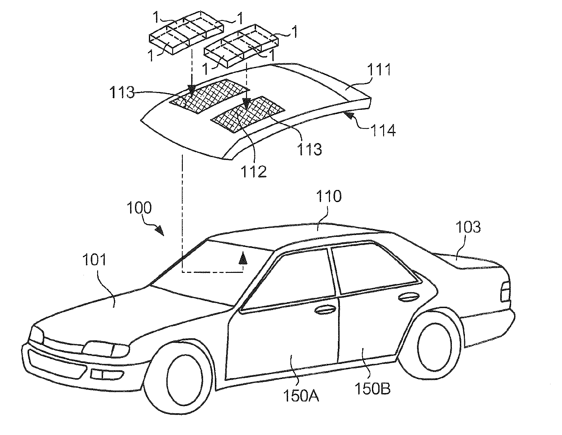
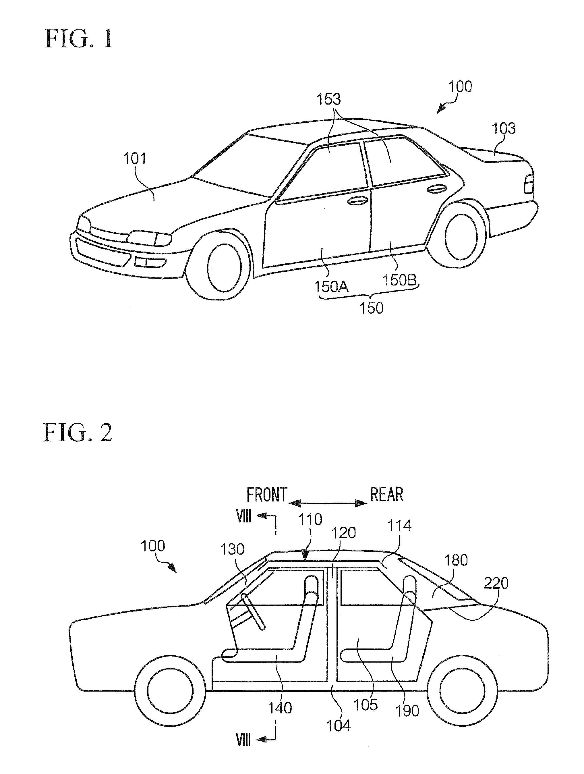
[0051]FIG. 1 is a perspective view showing the exterior appearance of a vehicle 100, i.e. a four-door sedan, equipped with an acoustic resonance device according to a first embodiment of the present invention. FIG. 2 diagrammatically shows a cabin / compartment 105 of the vehicle 100. Herein, a bonnet (hood) 101, four doors 150 (which serve as entrance doors of the compartment 105), and a trunk door 103 are fixed to a chassis (serving as a skeletal structure of the vehicle 100) in an open / close manner. The chassis of the vehicle 100 includes a base 104, center pillars 120 (which extend upwards from the base 104), front pillars 130, and rear pillars 180 as well as a part of a roof 110 (which is supported by those pillars). The compartment 105 is circumscribed by the doors 150 in the vehicle 100. The compartment 105 is a room space accommodating a driver / passenger who gets into the vehicle 100. A rear package tray 220 is installed in the rear side of the vehicle 100. ...

second embodiment

2. Second Embodiment

[0099]Next, a second embodiment of the present invention will be described with respect to an acoustic resonance device installed in the vehicle 100, which is constituted of a resonance pipe unit 2 including resonance pipes.

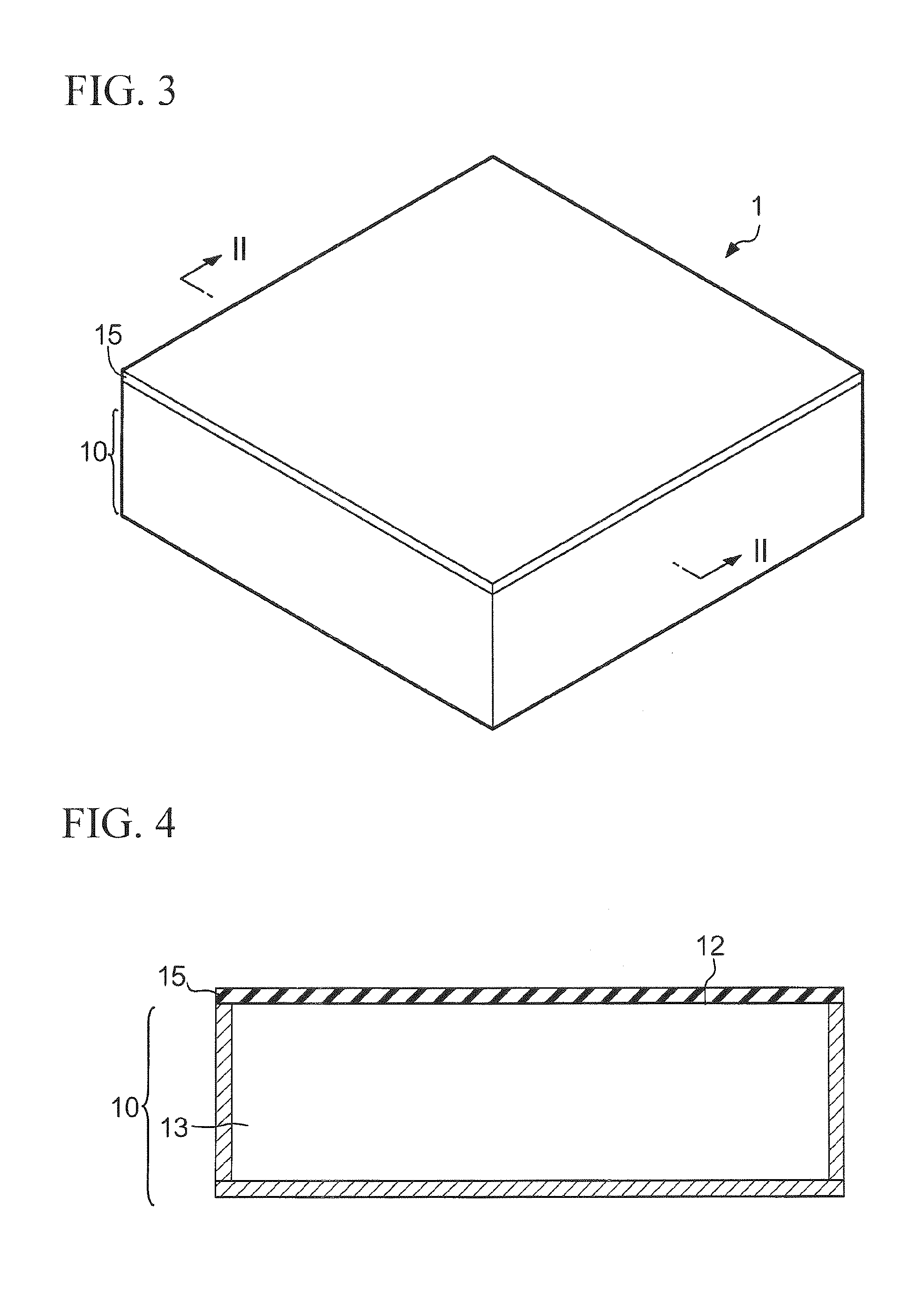
[0100]FIGS. 14A and 14B show the constitution of the resonance pipe unit 2. FIG. 14A shows the exterior appearance of the resonance pipe unit 2, which is constituted of five resonance pipes 21 (i.e. 21-1 through 21-5). The resonance pipes 21 are aligned in an alignment direction perpendicular to their longitudinal direction, wherein they are unified together via fixing measures or adhesive. The resonance pipes 21 are each composed of a metal or a synthetic resin, which is shaped in a pipe form. Each of the resonance pipes 21 is constituted of a closed end 22, an open end 23 and a hollow space 25; hence, it is a closed pipe having one open end and one closed end. The open ends 23 of the resonance pipes 21 are linearly aligned so as to adjoin to...

third embodiment

3. Third Embodiment

[0119]A third embodiment of the present invention is characterized by using a Helmholtz resonator 3, which is installed in the compartment 105. The third embodiment is similar to the first embodiment with respect to the overall structure of the vehicle 100 and the installation positions of resonators in the compartment 105, wherein the same constituent elements are designated the same numerals accompanied with a subscript “b”; hence, a detailed description thereof will be omitted.

[0120]The Helmholtz resonator 3 is employed as an acoustic resonance device of the third embodiment. FIG. 20A is a perspective view showing the exterior appearance of the Helmholtz resonator 3, and FIG. 20B is a cross-sectional view taken along line E-E in FIG. 20A. The Helmholtz resonator 3 is constituted of a body 31 and a tubular portion 32. A hollow space is formed inside the body 31 and the tubular portion 32 and communicates with an opening 33 of the tubular portion 32.

[0121]A cavit...


PUM


Abstract

An acoustic resonance device is installed in a compartment of a vehicle so as to reduce a low-frequency sound pressure (or noise) dependent upon a natural vibration. Specifically, an acoustic resonance device is a panel/diaphragm resonator, a resonance pipe, or a Helmholtz resonator, the inner space of which communicates with the compartment via an opening. The acoustic resonance device is positioned in proximity to an antinode of sound pressure owing to a natural vibration occurring in a driver/passenger space inside the compartment. Alternatively, the acoustic resonance device increases a particle velocity at a specific natural frequency or decreases sound pressure at an excitation frequency which occurs due to an external condition of the vehicle. The acoustic resonance device can be installed in a roof, a seat, a pillar supporting the roof, or a door of a vehicle.

Description

BACKGROUND OF THE INVENTION[0001]1. Field of the Invention[0002]The present invention relates to acoustic resonance devices which reduce sounds / noises in cabins / compartments of vehicles.[0003]The present application claims priority on Japanese Patent Application No. 2009-206496, the content of which is incorporated herein by reference.[0004]2. Description of the Related Art[0005]Conventionally, various technologies have been developed to improve quietness / noiselessness in cabins / compartments of vehicles by use of sound-absorbing materials. Patent Document 1 discloses a sound-absorbing material (e.g. a felt material) attached to a duct inside a dash panel in a cabin of a vehicle. Patent Document 2 discloses a panel / diaphragm sound-absorbing structure in which a panel / diaphragm vibrator and a rear cavity (or an air space in the rear of the vibrator) cooperate together to absorb sound.[0006]Even when the technology of Patent Document 1 adopts the sound-absorbing structure of Patent Doc...

Claims


Application Information

Patent Timeline
Patent Type & Authority Applications(United States)
IPC IPC(8): E04B1/82B60N2/90
CPCB60R13/0815
Inventor TANASE, RENTONAKASHIMA, HIROSHINAKAMURA, YASUTAKAFUKATSU, KEIICHIYOSHIDA, ATSUSHIKATO, SHINICHI
Owner YAMAHA CORP
Why Eureka
Try Eureka