Cleaning module and EUV lithography device with cleaning module

a technology of cleaning module and lithography device, which is applied in the field of cleaning modules, can solve the problems of surface damage, damage to the surface, and affect the optical characteristics of the printed image, and achieve the effect of gentle cleaning of the optical elements and the improvement of the known cleaning head

Inactive Publication Date: 2011-03-10
CARL ZEISS SMT GMBH
View PDF11 Cites 31 Cited by
  • Summary
  • Abstract
  • Description
  • Claims
  • Application Information

AI Technical Summary

Benefits of technology

[0008]It is an object of the present invention to improve the known cleaning heads to the effect that a gentler cleaning of the optical elements is enabled.

Problems solved by technology

The problem with the previous approach is that on the one hand the cleaning heads should be arranged relatively closely to the mirrors in order to obtain a high degree of cleaning efficiency.
Heating up the mirrors too much during cleaning leads to an impairment of their optical characteristics.
A further problem consists in the fact that ionized particles can be produced when using known cleaning heads, which ionized particles are accelerated towards the mirror surface to be cleaned and could lead to damage to the surface by way of a sputter effect.

Method used


Image

  • Cleaning module and EUV lithography device with cleaning module
  • Cleaning module and EUV lithography device with cleaning module
  • Cleaning module and EUV lithography device with cleaning module

Examples


Embodiment Construction

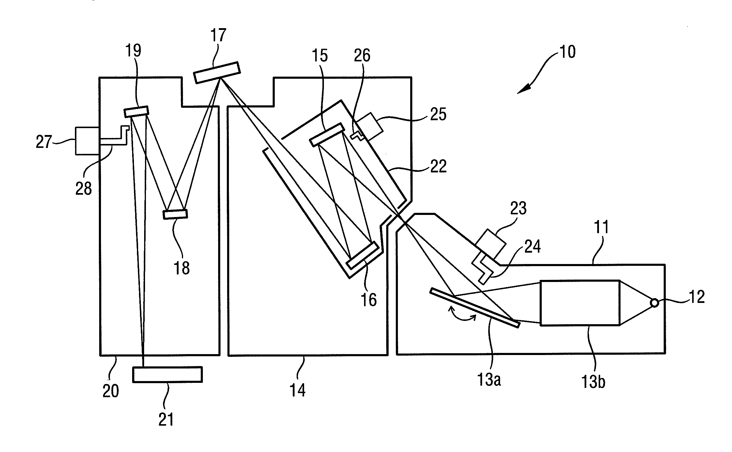
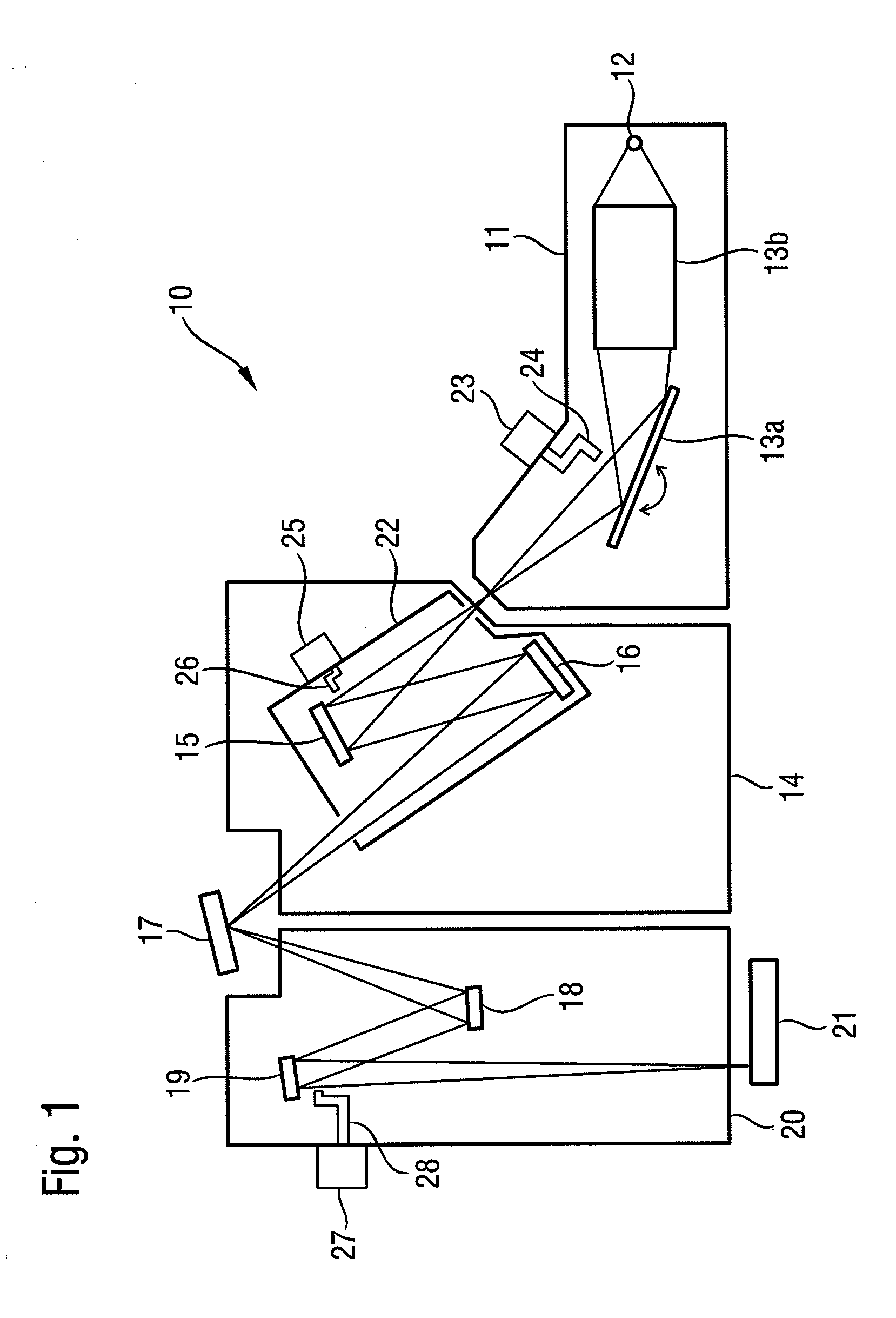
[0035]FIG. 1 schematically shows an EUV lithography device 10. Primary components are the beam forming system 11, the exposure system 14, the photomask 17 and the projection system 20. The EUV lithography device 10 is operated under vacuum conditions so that the EUV radiation in its interior is absorbed as little as possible.

[0036]A plasma source or also a synchrotron can be used as a radiation source 12, for example. The emitting radiation in the wavelength range from approximately 5 nm to 20 nm is initially focussed in the collimator 13b. In addition, the desired operating wavelength is filtered out by varying the angle of incidence with the aid of a monochromator 13a. In the wavelength range mentioned, the collimator 13b and the monochromator 13a are usually configured as reflective optical elements. Collimators are often reflective optical elements which are configured to be bowl-shaped in order to achieve a focussing or collimating effect. The radiation is reflected on the conc...


PUM

PropertyMeasurementUnit
bending angleaaaaaaaaaa
wavelength rangeaaaaaaaaaa
bending anglesaaaaaaaaaa

Abstract

A cleaning module for an EUV lithography device with a supply (206) for molecular hydrogen, a heating filament (210) and a line (212) for atomic and / or molecular hydrogen. The line (212) has at least one bend with a bending angle of less than 120 degrees, and has a material on its inner surface which has a low recombination rate for atomic hydrogen. The supply (206) is of flared shape at its end, which faces the heating filament (210). A gentler cleaning of optical elements is achieved with such a cleaning module, or also by exciting a cleaning gas with a cold cathode or a plasma, or by filtering out charged particles via of electrical and / or magnetic fields.

Description

[0001]This is a Continuation of International Application PCT / EP2008 / 009754, with an international filing date of Nov. 19, 2008, which was published under PCT Article 21(2) in English, and which claims priority to DE 10 2008 000 959.8 filed Apr. 3, 2008, to U.S. 61 / 042,061 filed Apr. 3, 2008, to DE 10 2008 040 720.8 filed Jul. 25, 2008, and to U.S. 61 / 083,811 filed Jul. 25, 2008, the entire disclosures of which, including amendments, are incorporated into this application by reference.FIELD OF THE INVENTION AND BACKGROUND[0002]The present invention relates to cleaning modules, in particular for an EUV lithography device, with a supply for a cleaning gas and a device for exciting the cleaning gas, as well as to a cleaning module, in particular for an EUV lithography device, with a supply for molecular hydrogen and a heating filament.[0003]The present invention further relates to an EUV lithography device with such a cleaning module and to a projection system and to an exposure system...

Claims


Application Information

Patent Timeline
Patent Type & Authority Applications(United States)
IPC IPC(8): G03B27/52C23F1/08
CPCG03F7/70925B08B7/0035
Inventor EHM, DIRK HEINRICHKALLER, JULIANSCHMIDT, STEFANKRAUS, DIETERWIESNER, STEFANCZAP, ALMUTCHUNG, HIN-YIU ANTHONYKOEHLER, STEFAN
Owner CARL ZEISS SMT GMBH
Why Eureka
Try Eureka