
TOF Range Finding With Background Radiation Suppression

a technology of background radiation and range finding, applied in the direction of optical radiation measurement, distance measurement, instruments, etc., can solve the problems of reducing the signal to noise ratio and distance accuracy, reducing the dynamic range of the upper end, and efficiently separating signals originating from background ligh

Active Publication Date: 2011-03-10
SOFTKINETIC SENSORS
View PDF12 Cites 35 Cited by
  • Summary
  • Abstract
  • Description
  • Claims
  • Application Information

AI Technical Summary

Benefits of technology

[0011]It is an object of embodiments of the present invention to provide good apparatus or methods for performing TOF measurements.
[0041]It is an advantage of embodiments of the present invention that range finding methods and systems based on TOF measurements are improved compared to prior art methods and systems.
[0042]It is a further advantage of embodiments of the present invention that range finding methods and systems based on TOF measurements using small area circuits supporting 2D-arrays of rangefinders are provided, to thereby provide 3D-cameras for many applications.
[0043]It is an advantage of embodiments of the present invention that an integrating circuit with high background light attenuation is achieved keeping high signal to noise ratio and still achieving 3D camera operation.

Problems solved by technology

A problem is to separate signals originating from background light efficiently from signals originating from useful TOF-light.
Therefore this solution adds transistor noise to the circuit, thus degrading the signal to noise ratio and distance accuracy.
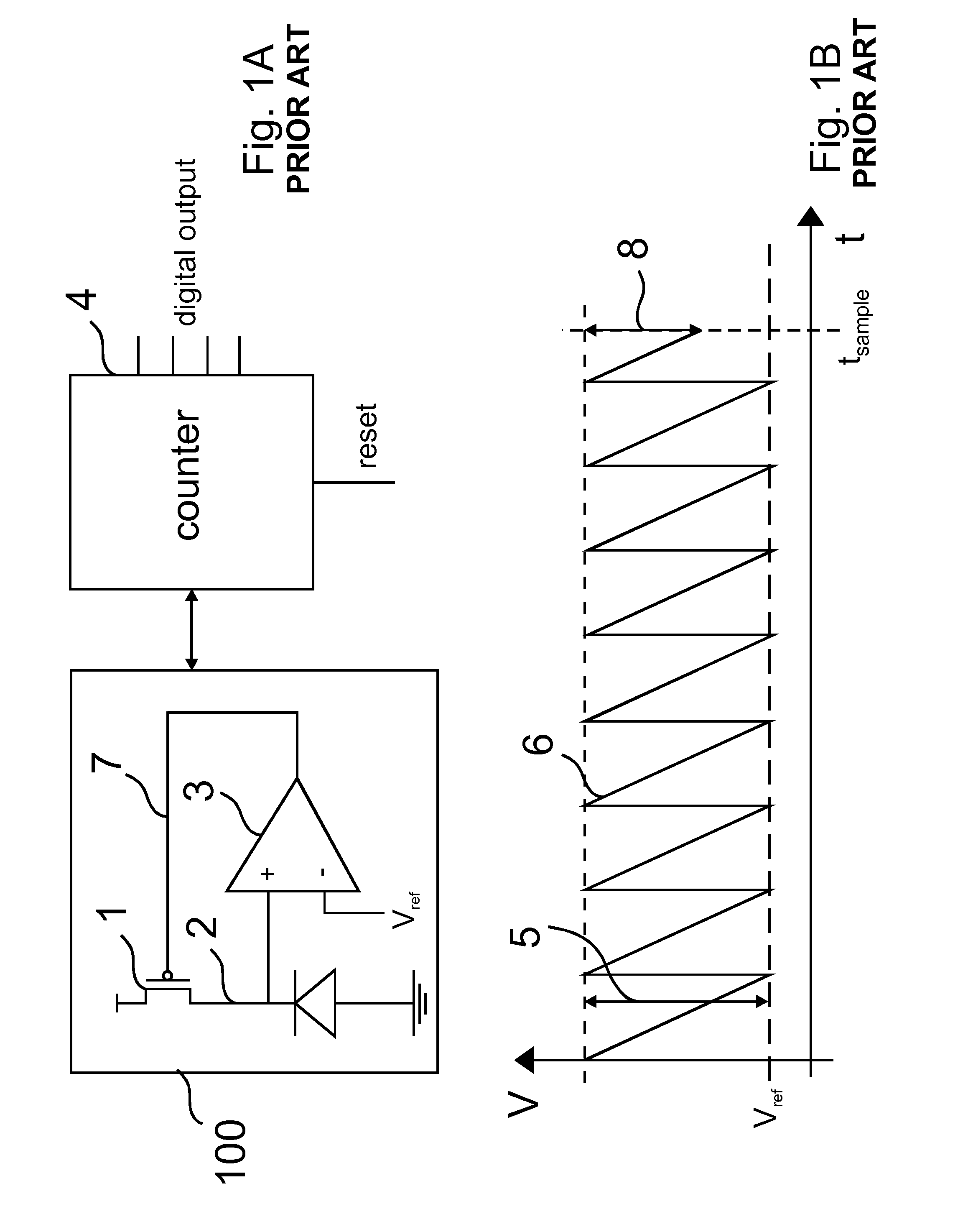
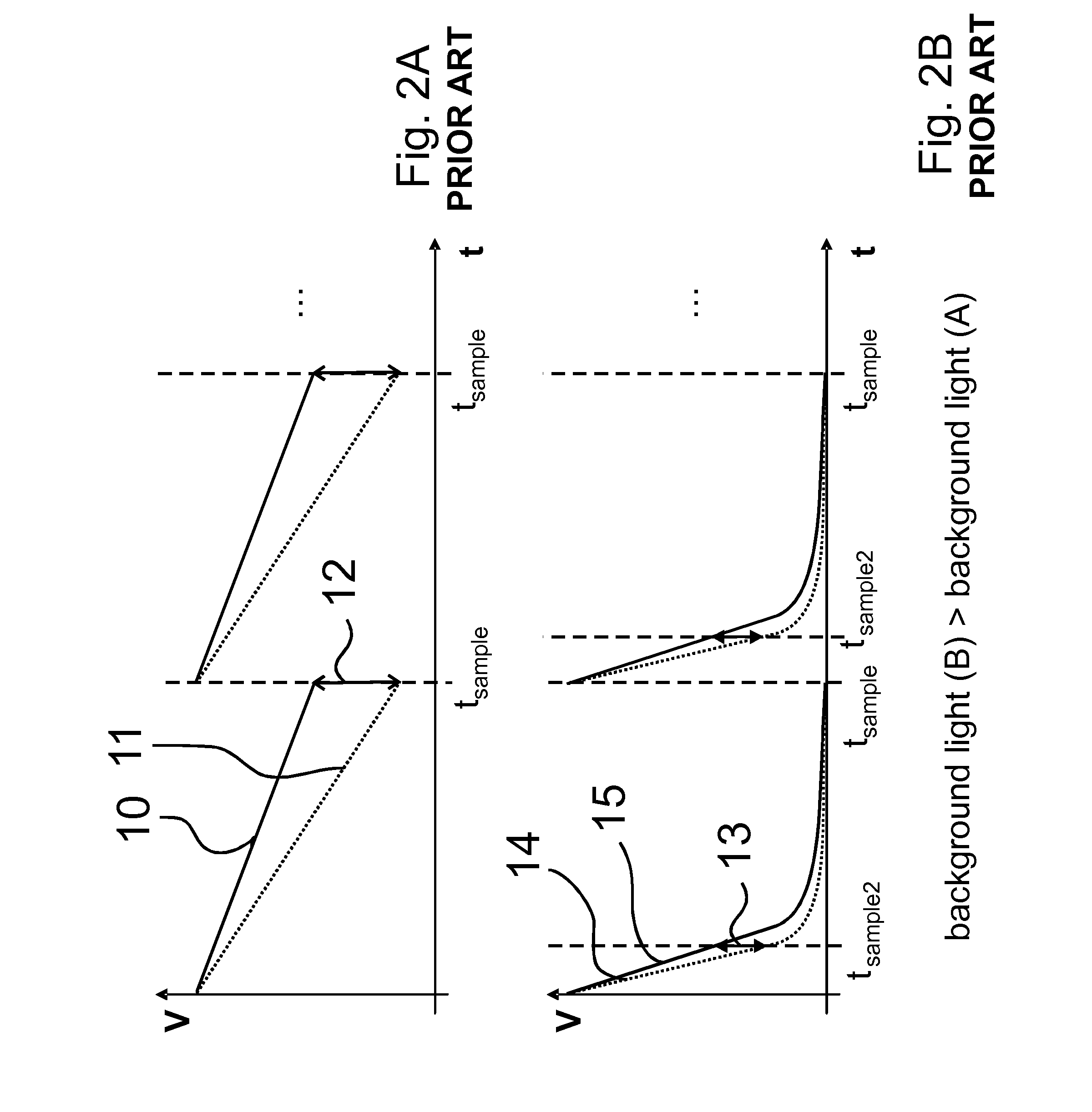
Major drawback of the approach is the limited upper end dynamic range due to saturation of the capacitor.
Capacitance integration has been reused in TOF imaging to similarly optimize signal to noise ratio, but unfortunately, due to this limited upper end dynamic range for both useful and background light, rapidly fails in the presence of background light.
However, since in these techniques the amount of needed circuitry scales with the achieved dynamic range extension, for obtaining reasonable background light suppression a very large substrate area, e.g. silicon area, is needed.

Method used


Image

  • TOF Range Finding With Background Radiation Suppression
  • TOF Range Finding With Background Radiation Suppression
  • TOF Range Finding With Background Radiation Suppression

Examples


Embodiment Construction

[0108]The present invention will be described with respect to particular embodiments and with reference to certain drawings but the invention is not limited thereto but only by the claims. The drawings described are only schematic and are non-limiting. In the drawings, the size of some of the elements may be exaggerated and not drawn on scale for illustrative purposes. The dimensions and the relative dimensions as illustrated do not correspond to actual reductions to practice of the invention.

[0109]Furthermore, the terms first, second, third and the like in the description and in the claims, are used for distinguishing between similar elements and not necessarily for describing a sequence, either temporally, spatially, in ranking or in any other manner. It is to be understood that the terms so used are interchangeable under appropriate circumstances and that the embodiments of the invention described herein are capable of operation in other sequences than described or illustrated he...


PUM


Abstract

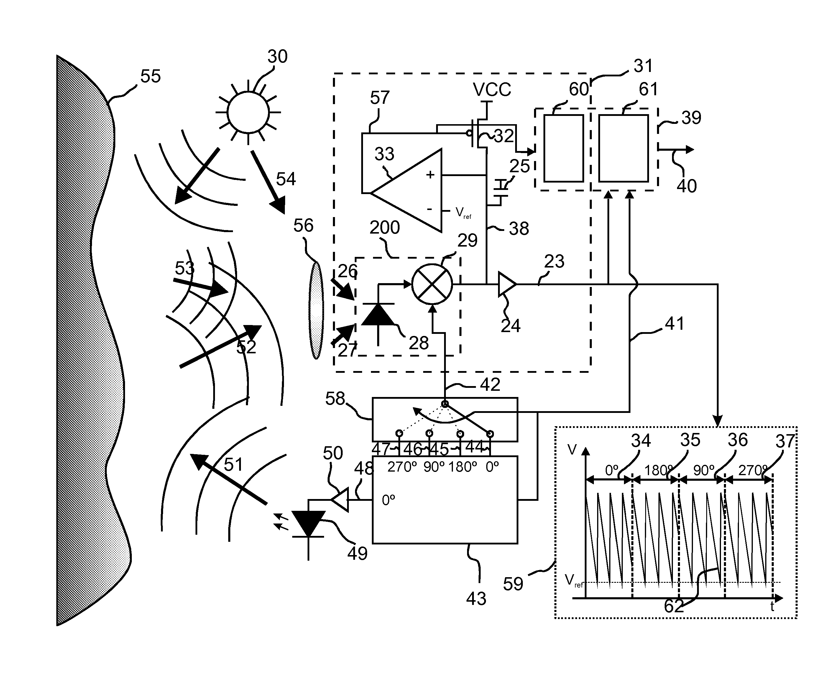
A method for measuring time of flight of radiation includes emitting modulated radiation (51) in response to a first modulation signal, projecting the modulated radiation (51) onto a scene (55), and receiving radiation, the received radiation including at least modulated radiation reflected by the scene (55). The received radiation (26, 27) is converted into a radiation induced electrical signal. The radiation induced electrical signal is mixed with a second modulation signal, thus generating a mixed signal, which is integrated, thus generating an integrated signal. When the integrated signal exceeds a threshold value (Vref), charge is injected into the integrated signal. The method includes applying changes to the first and / or second modulation signal at one or more moments in time, and measuring the integrated signal at one or more moments in time, thus obtaining at least one TOF pair difference signal (62). The measuring includes using a single detector node (38) and associated memory element (25), to obtain a TOF pair difference signal (62). The method furthermore includes using one or more TOF pair difference signals to determine time of flight of radiation.

Description

TECHNICAL FIELD OF THE INVENTION[0001]The present invention relates to the field of distance measuring sensors and methods for time-of-flight (TOF) measurements. More particularly the present invention relates to such devices and methods adapted to achieve efficient background radiation handling, in particular to achieve efficient background radiation suppression, at variable background radiation conditions. The radiation may be visible or infrared light.BACKGROUND OF THE INVENTION[0002]The basic principle of using time-of-flight (TOF) measurements for range finding applications is to measure how long it takes for radiation, e.g. photons to travel over an unknown distance. The unknown distance can then be deduced from the measured time of flight in combination with the known speed of the radiation such as light.[0003]Many ways of how to modulate a light source for such TOF measurements, and which strategy to follow for making the distance measurement are known to a person skilled in...

Claims


Application Information

Patent Timeline
IPC IPC(8): G01C3/08G01J5/02H04N5/355
CPCG01S17/08G01S7/4876H04N5/35572H04N25/587G01S7/487
Inventor VAN NIEUWENHOVE, DANIELVAN DER TEMPEL, WARDKUIJK, MAARTEN
Owner SOFTKINETIC SENSORS
Learn More