
Low dropout regulator

Active Publication Date: 2011-03-17
ACER INC
View PDF11 Cites 6 Cited by
  • Summary
  • Abstract
  • Description
  • Claims
  • Application Information

AI Technical Summary

Benefits of technology

[0010]In view of the aforementioned problems of the prior art, the primary object of the present invention is to provide a low dropout regulator that receives an input power from a Li-ion battery or a rechargeable battery, and provides a stable voltage output given different loads.
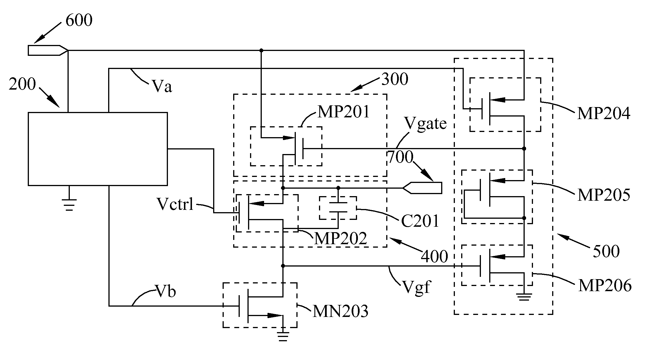
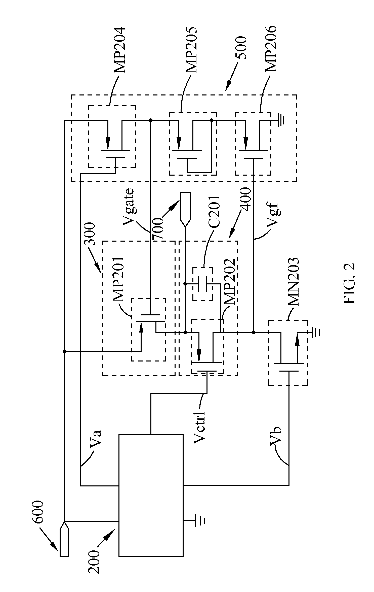
[0011]According to the object of the present invention, the low dropout regulator is provided, comprising a reference circuit, a power transfer element, a regulating circuit, and a lever regulating device. The reference circuit provides a comparing voltage and bias voltage sources to the regulating circuit and the level regulating device. The power transfer element provides different output power during switching between different loads. The regulating circuit detects a voltage change at the output terminal due to a load change, amplifies the voltage change, and transmits the amplified voltage change to the level regulating device; the regulating circuit also utilizes common gate amplification to add a compensating capacitor to achieve phase compensation so as to maintain the stability of the circuit. The level regulating device boosts the received signal based on the amplified voltage change and transmits the boosted signal to the power transfer element.
[0013]With the above arrangements, the low dropout regulator of the present invention attains the following advantages:
[0014](1) The low dropout regulator may be applicable to an input power from a Li-ion battery, and provides stable output power given different load changes without any external load capacitor.

Problems solved by technology

However, conventional low dropout regulators, such as that disclosed in Taiwan Patent No. 200534070, often require external load capacitors to stabilize and boost transient response.
Therefore, it has become a critical issue of developing a low dropout regulator that does not require external passive elements or requires only very few number of passive elements.
However, all of the low dropout regulators proposed in the above articles may not be applied to a power supply with a relatively large input range.

Method used


Image

  • Low dropout regulator
  • Low dropout regulator
  • Low dropout regulator

Examples


Embodiment Construction

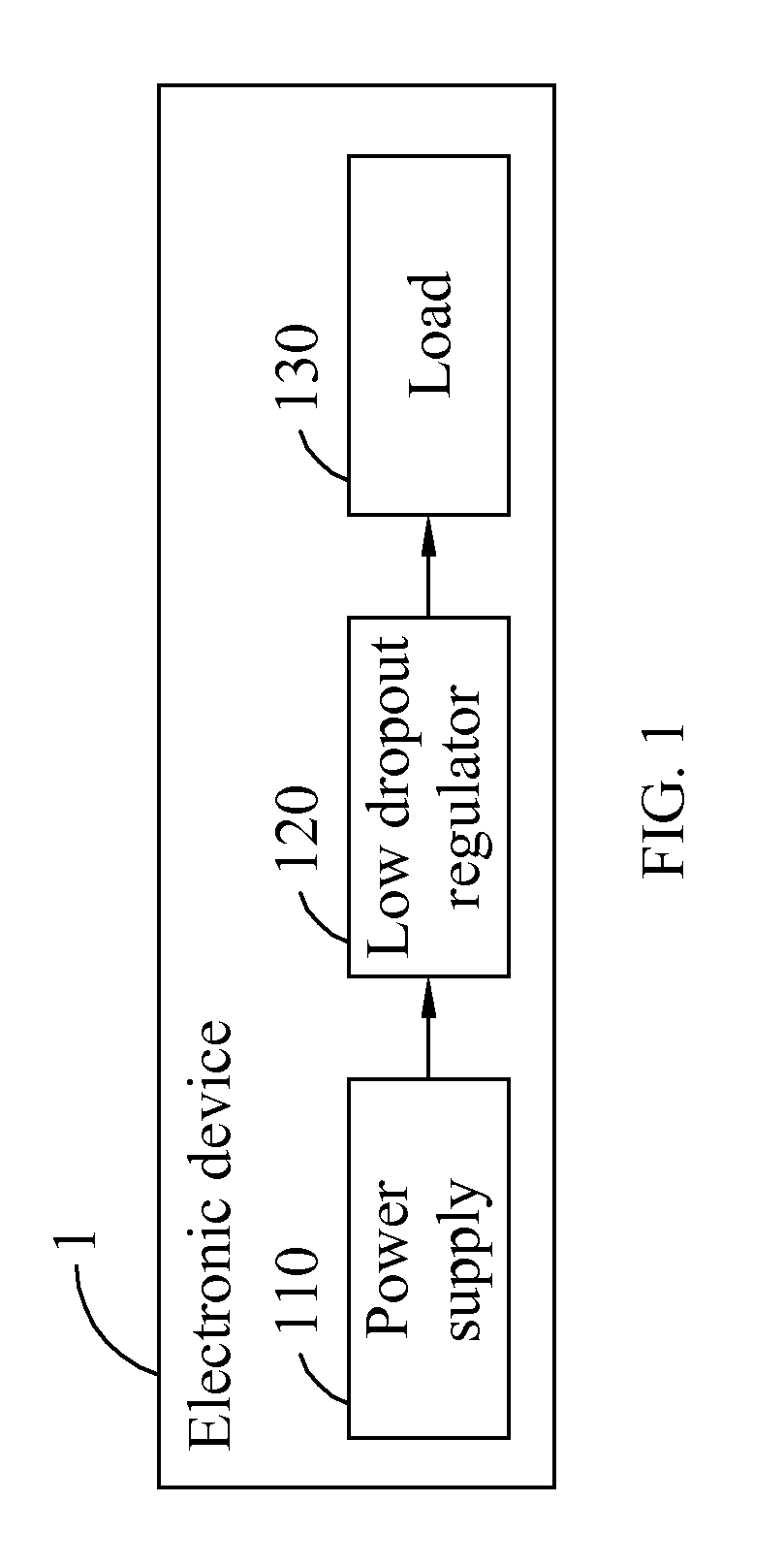
[0024]Referring to FIG. 1, a block diagram of an electronic device 1 with a low dropout regulator according to the present invention is illustrated. As shown in the figure, the electronic device 1 includes a power supply 110, a low dropout regulator 120, and a load 130. Preferably, the power supply 110 is a Li-ion battery or a rechargeable battery providing a voltage source between 4.2˜3.3V. An unstable input power form the power supply 110 is converted into a stable output power by the low dropout regulator 120 in responsive to changes at the load 130. The load 130 may be any circuit that requires a stable voltage source.

[0025]Please refer to FIG. 2. A circuit diagram of a low dropout regulator according to a preferred embodiment of the present invention is illustrated. As shown in the figure, the low dropout regulator comprises a reference circuit 200, a power transfer element 300, a regulating circuit 400, a level regulating device 500, a first N-type metal-oxide-semiconductor fi...


PUM


Abstract

The present invention relates to a low dropout regulator, and more particularly to a low dropout regulator without load capacitor and ESR (equivalent series resistance) designed in response to the discharge curve of a Li-ion battery, includes an input terminal, a reference circuit, a power transfer element, a level regulating device, a regulating circuit, and a first N-type MOSFET. The regulating circuit detects a load change at an output terminal, amplifies the load change, and couples it to the level regulating device. The level regulating device receives and boosts a received signal and transmits the received signal to the power transfer element, so as to achieve the effect of controlling the power of a power supply.

Description

FIELD OF THE INVENTION[0001]The present invention relates to a low dropout regulator (LDO), and more particularly to a low dropout regulator without load capacitor and ESR (equivalent series resistance) designed in response to the discharge curve of a Li-ion battery.BACKGROUND OF THE INVENTION[0002]When a Li-ion battery is used as a power supply, the voltage of the battery end will drop from 4.2V to 3.3V during the discharging process. Therefore, a voltage regulator is needed to regulate the battery voltage to a stable voltage for supplying to an electronic product. Hence, a low dropout regulator is most suitable for this purpose under the premise of reducing volume.[0003]However, conventional low dropout regulators, such as that disclosed in Taiwan Patent No. 200534070, often require external load capacitors to stabilize and boost transient response. Therefore, it has become a critical issue of developing a low dropout regulator that does not require external passive elements or re...

Claims


Application Information

Patent Timeline
IPC IPC(8): G05F1/10
CPCG05F1/575G05F1/56
Inventor WANG, CHUA-CHINYEN, SHAO-FU
Owner ACER INC
Learn More