
Three-phase four-wire system inverter circuit

A three-phase four-wire system, three-phase inverter technology, applied in electrical components, irreversible DC power input into AC power output, AC power input into DC power output and other directions, can solve the problem of uneven output voltage, etc. problem, to achieve the effect of small changes and increased load capacity

Inactive Publication Date: 2008-09-24
黄敬党
View PDF1 Cites 2 Cited by
  • Summary
  • Abstract
  • Description
  • Claims
  • Application Information

AI Technical Summary

Problems solved by technology

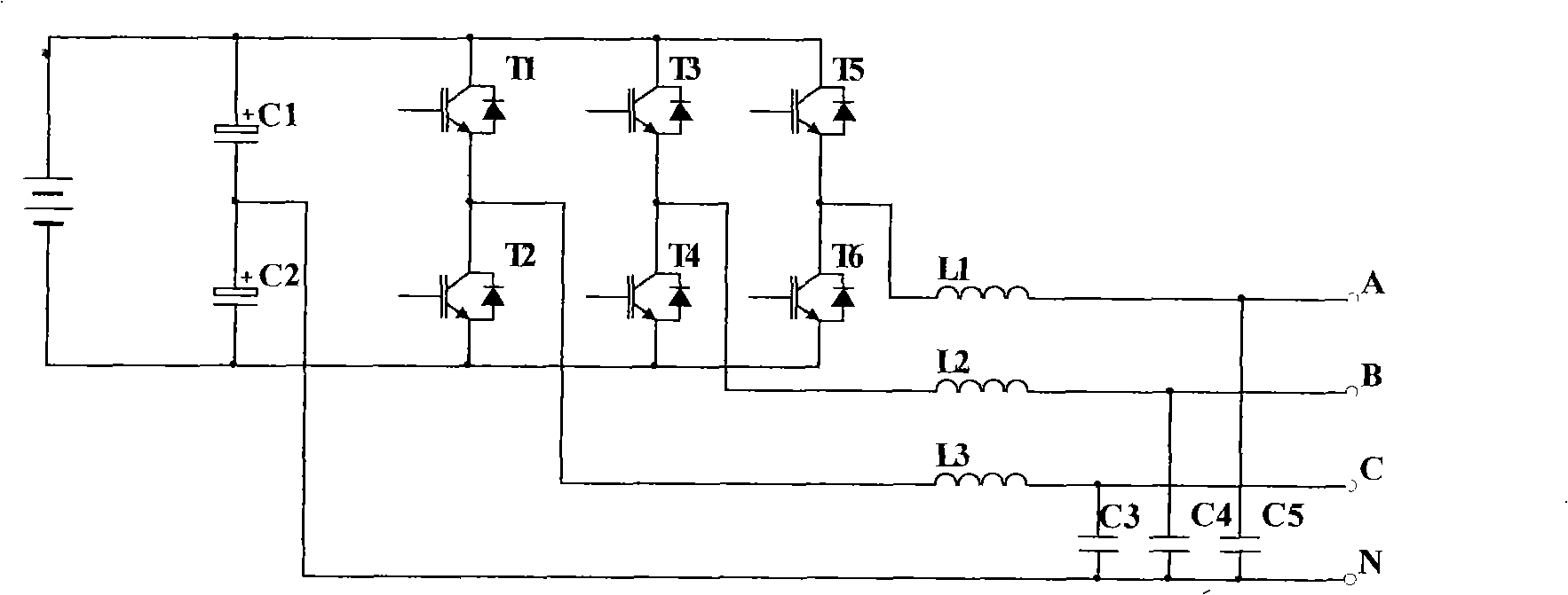
[0002] China Patent Network discloses a three-phase four-wire system inverter power supply, the application number is: 01107245.8, its circuit principle is as follows figure 1 As shown, the potential of the neutral point N will change when the load is asymmetrical in this circuit, which directly leads to uneven output voltage

Method used


Image

  • Three-phase four-wire system inverter circuit
  • Three-phase four-wire system inverter circuit
  • Three-phase four-wire system inverter circuit

Examples


Embodiment 1

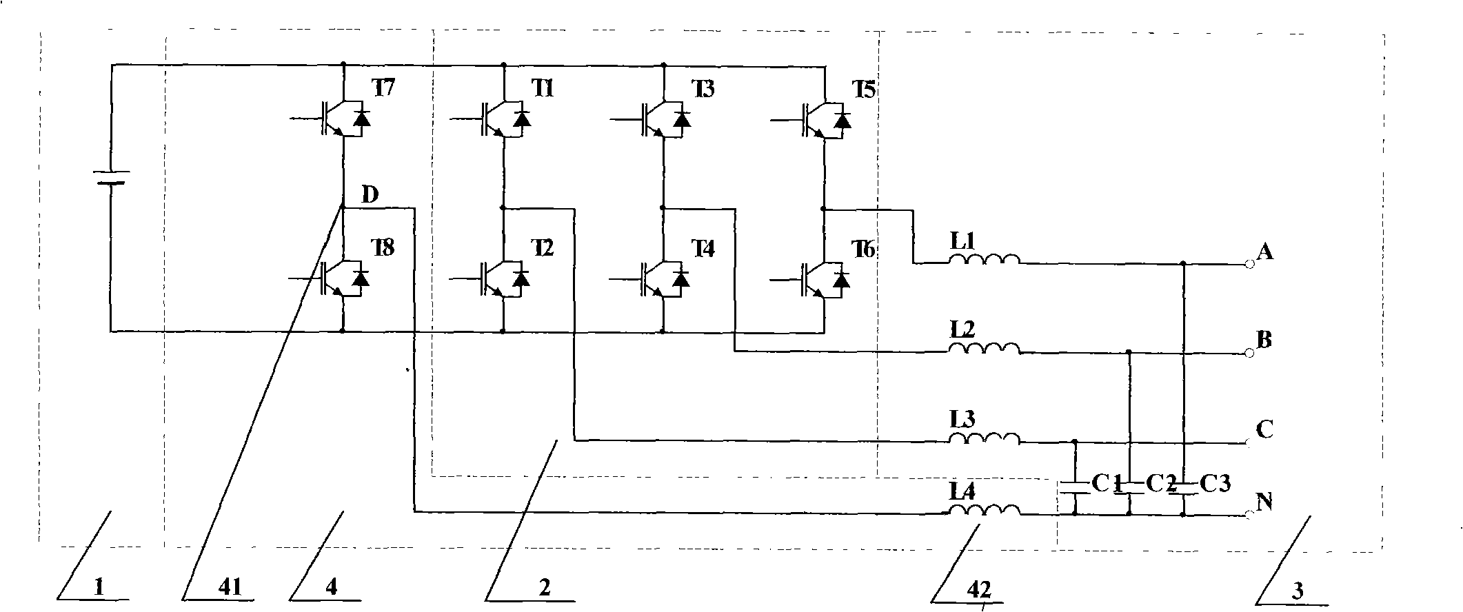
[0014] Example 1, such as figure 2 As shown, a three-phase four-wire inverter circuit includes a DC power supply 1, a three-phase inverter circuit 2, and an AC filter circuit 3. The point adjustment circuit 4 is connected between the DC power supply 1 and the AC filter circuit 3. The neutral point adjustment circuit 4 generally consists of a bridge arm circuit 41 and an inductance 42 connected to its middle point D. The other end of the inductance 42 is connected to the inverter Transformer neutral point N. The power transistor in the bridge arm circuit 41 is an IGBT, or a GTO, or a MOSFET, or a thyristor. The circuit should use higher power transistors.

Embodiment 2

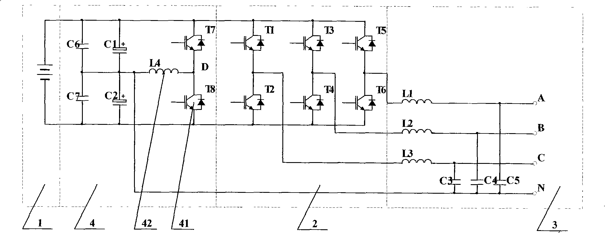
[0015] Example 2, such as image 3 As shown, a three-phase four-wire inverter circuit includes a DC power supply 1, a three-phase inverter circuit 2, and an AC filter circuit 3. The point adjustment circuit 4 is connected between the DC power supply 1 and the AC filter circuit 3. The neutral point adjustment circuit 4 is composed of a bridge arm circuit 41 and an inductance 42 connected to its midpoint D. The other end of the inductance 42 passes through two equal-capacity The capacitors (C1 and C2) are respectively connected to the two poles of the DC power supply, and at the same time connected to the neutral point N of the inverter for output. C6 and C7 are small capacitors that play the role of filtering high frequencies. The power transistor in the bridge arm circuit 41 is an IGBT, or a GTO, or a MOSFET, or a silicon controlled rectifier. Since there are capacitors C1 and C2, a small power transistor can be selected.


PUM


Abstract

The invention belongs to an inverse circuit, in particular to a three-phase four-wire inverter circuit. The invention relates to a three-phase four-wire inverter circuit which comprises a DC power supply, a three-phase inverse circuit and an AC filter circuit that are connected in sequence; the invention is mainly characterized in that a neutrality point adjusting circuit is connected with the three-phase inverse circuit in parallel and is connected between the DC power supply and the AC filter circuit. The circuit of the invention has the advantages of creatively adding a neutrality point in the circuit and compulsorily leading the voltages of the two ends to maintain consistent; the elements added are fewer and the alternation to the original circuit is less, but the output end of the three-phase four-wire inverter circuit can output stable voltage even if the loads are not symmetrical, thus increasing the loading capacity of the inverter.

Description

technical field [0001] The invention belongs to an inverter circuit, in particular to a three-phase four-wire inverter circuit. Background technique [0002] China Patent Network discloses a three-phase four-wire system inverter power supply, the application number is: 01107245.8, its circuit principle is as follows figure 1 As shown, the potential of the neutral point N will change when the load of the circuit is asymmetrical, which directly leads to uneven output voltage. Contents of the invention [0003] The purpose of the present invention is to overcome the above disadvantages and provide a three-phase four-wire inverter circuit that can ensure uniform output voltages of each circuit even when the load is asymmetrical. [0004] The technical solution adopted in the present invention is a three-phase four-wire inverter circuit, including a DC power supply, a three-phase inverter circuit, and an AC filter circuit. A neutral point adjustment circuit is connected in pa...

Claims


Application Information

Patent Timeline
Patent Type & Authority Applications(China)
IPC IPC(8): H02M7/48H02M1/12H02M7/5387H02M7/521
Inventor 黄敬党
Owner 黄敬党
Learn More