Image display device

a display device and image technology, applied in the field of image display devices, can solve the problems of reducing thickness and damage to the panel, and achieve the effects of suppressing a decrease in strength, reducing the thickness of the portion, and reducing the apparent thickness

Inactive Publication Date: 2011-03-17
PANASONIC INTELLECTUAL PROPERTY MANAGEMENT CO LTD
View PDF7 Cites 12 Cited by
  • Summary
  • Abstract
  • Description
  • Claims
  • Application Information

AI Technical Summary

Benefits of technology

[0012]According to the image display device of the present invention, the circuit boards are arranged concentrically, and these circuit boards are accommodated in the projecting portion of the back cover. Therefore, it is possible to reduce the thickness of the portion defined by the edge portion located outside the projecting portion, thus allowing the apparent thickness to be reduced. Furthermore, it is possible to suppress a decrease in strength by providing the drawn portions in the edge portion. That is, an image display device that can achieve a reduction in thickness, while preventing the strength from decreasing, can be obtained.

Problems solved by technology

However, such a configuration has a problem in that the strength of the portion having a reduced thickness decreases, which may cause the panel to be damaged if the device is dropped or subjected to an external force.

Method used


Image

  • Image display device
  • Image display device
  • Image display device

Examples


first embodiment

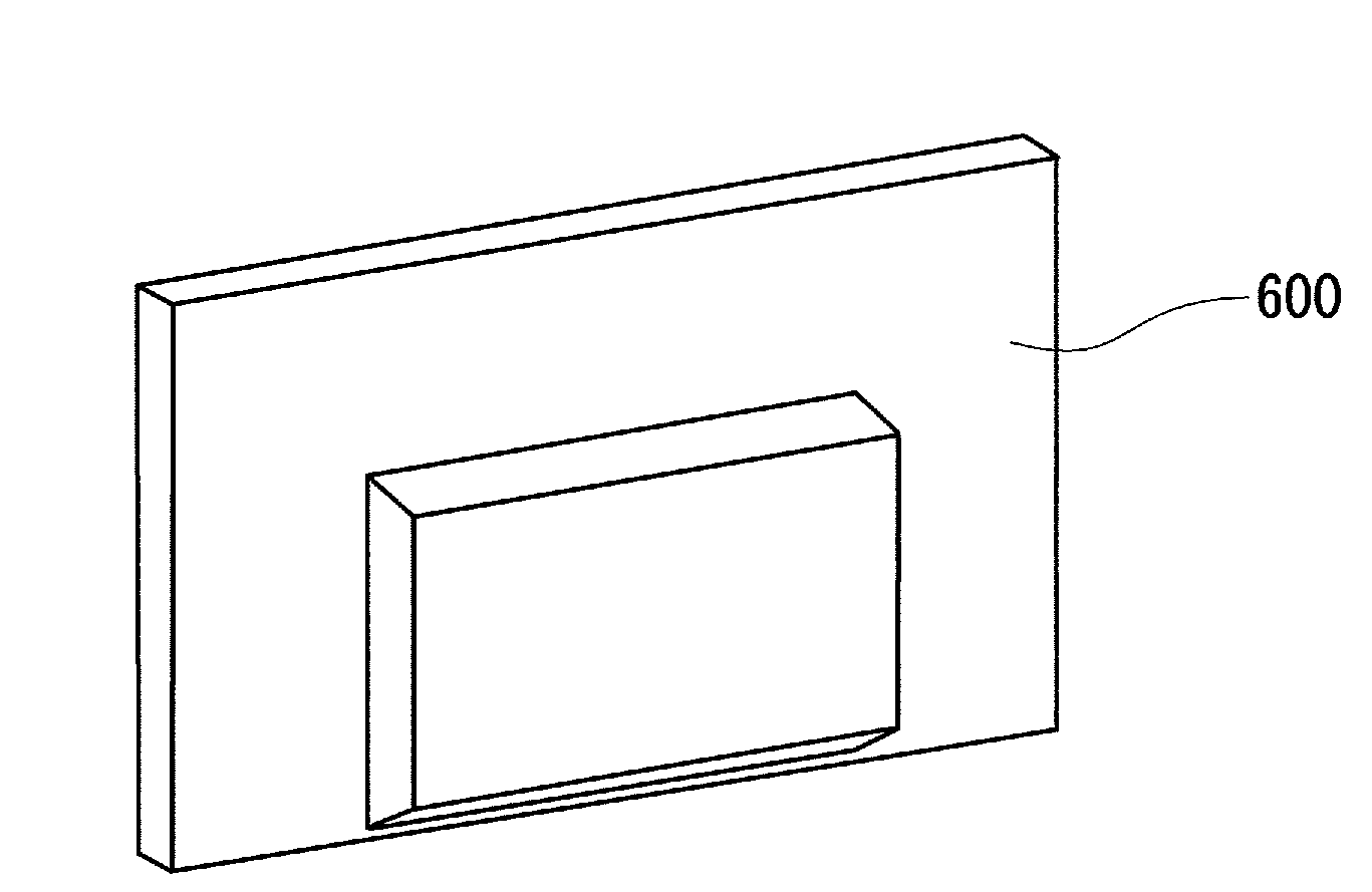
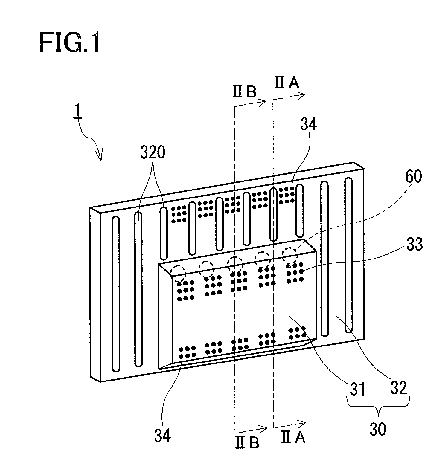
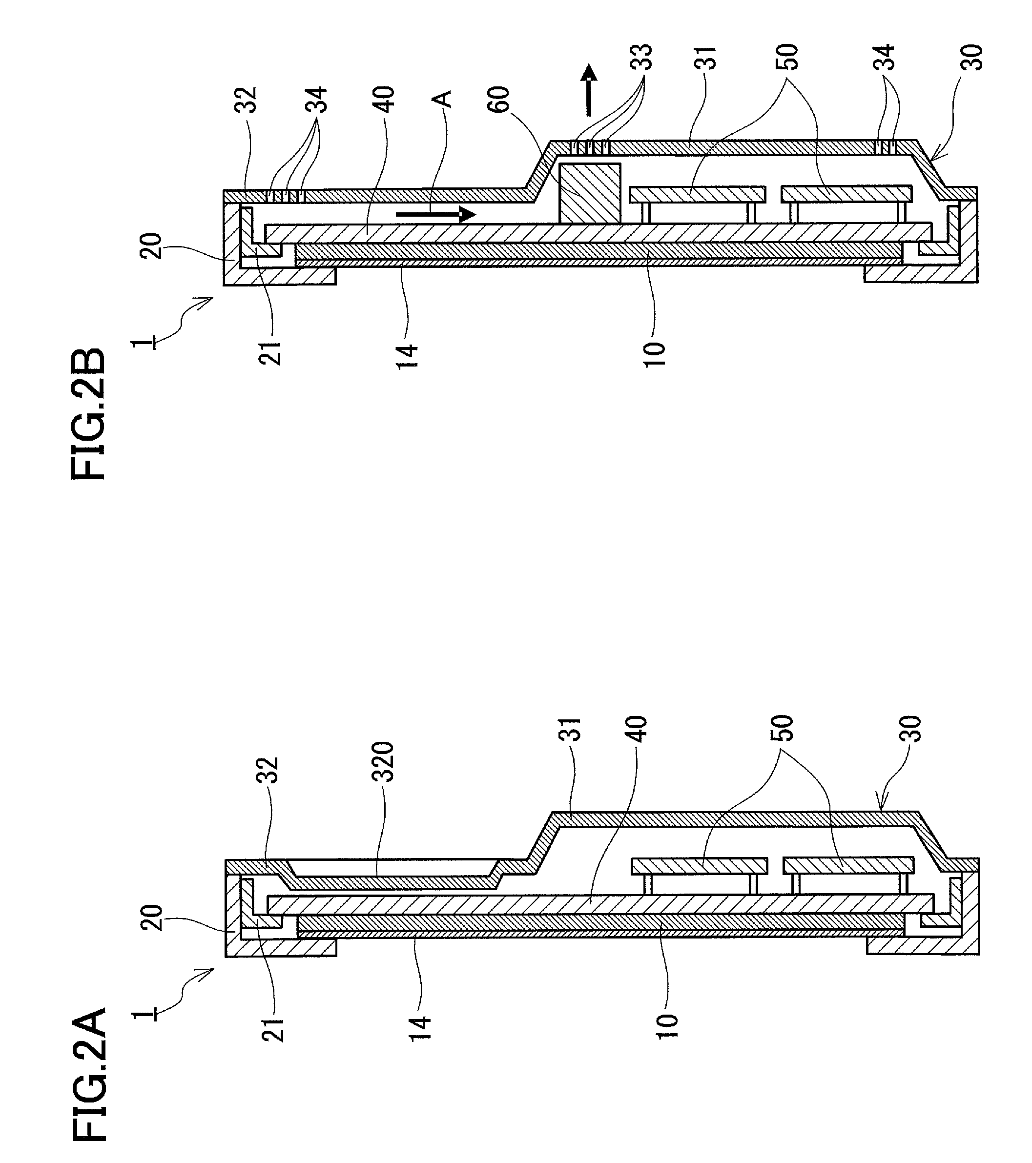
[0021]FIG. 1 is a perspective view illustrating a configuration of a plasma display device 1 according to the first embodiment of the present invention. FIG. 2A is a sectional view taken along the line IIA-IIA in FIG. 1, and FIG. 2B is a sectional view taken along the line IIB-IIB in FIG. 1. FIG. 3 is an enlarged partial view of FIG. 2A.

[0022]The plasma display device 1 is provided with a front cover 20 and a back cover 30. A PDP 10 as a display panel for displaying images, a chassis 40 supporting the PDP 10 on its front surface, and a plurality of circuit boards 50 that are mounted to the back surface of the chassis 40 for driving the PDP 10 are accommodated inside the space surrounded by the front cover 20 and the back cover 30. The plasma display device 1 has an elongated shape, viewed from the image display screen side, and generally is positioned such that the longitudinal direction is the horizontal direction and the short direction is the vertical direction (that is, the PDP ...

second embodiment

[0041]Next, the second embodiment of the present invention is described with reference to FIG. 4 and FIG. 5. The second embodiment differs from the first embodiment in that the concave portions 320 are in contact with the back surface of the chassis 40. Other configurations are the same as those in the first embodiment and thus descriptions thereof are omitted.

[0042]FIG. 4 is a sectional view including the concave portions 320 in the plasma display device 2 according to the second embodiment, and corresponds to FIG. 2A in the first embodiment.

[0043]In the plasma display device 2, the concave portions 320 provided in the edge portion 32 of the back cover 30 are in contact with the back surface of the chassis 40 via heat transfer sheets 70 with heat conductivity. As a material to form the heat transfer sheet 70, silicon, acrylic, or the like can be used, for example.

[0044]Each of the heat transfer sheets 70 has a strip shape with about the same length and width as the concave portions...


PUM


Abstract

The image display device is provided with a panel for displaying images, a chassis supporting the display panel on its front surface, circuit boards arranged within a specific region of the back surface of the chassis, and a back cover having an edge portion that covers the outside of the specific region of the back surface of the chassis, and a projecting portion that projects inside the edge portion toward the side opposite to the chassis and that accommodates the circuit boards. The edge portion has a plurality of drawn portions extending toward a particular direction.

Description

BACKGROUND OF THE INVENTION[0001]1. Field of the Invention[0002]The present invention relates to an image display device for displaying images, such as television images.[0003]2. Description of Related Art[0004]In recent years, with a reduction in thickness of image display devices for displaying images such as television images, image display devices using a so-called flat display panel such as a plasma display panel and a liquid crystal panel have become mainstream, instead of conventional CRTs.[0005]FIG. 6 is a schematic sectional view showing an internal configuration of a plasma display device as an example of such a flat image display device. It should be noted that the upward and downward direction means the upward and downward direction (that is, the vertical direction) of a plasma display device in the normal use position (that is, laterally placed), and the left and right direction means a direction orthogonal to this (that is, the horizontal direction) in the following de...

Claims


Application Information

Patent Timeline
Patent Type & Authority Applications(United States)
IPC IPC(8): H04N5/64
CPCH04N5/64H05K7/20954H05K5/02
Inventor NAKASE, KIYOTAKA
Owner PANASONIC INTELLECTUAL PROPERTY MANAGEMENT CO LTD
Why Eureka
Try Eureka