Electronic device with a heat insulating structure

a technology of electronic devices and heat insulation, which is applied in the direction of electrical apparatus, electrical apparatus casings/cabinets/drawers, cooling/ventilation/heating modifications, etc., can solve the problems of low heat dissipation efficiency of plastic enclosures, easy affecting the operation stability of electronic devices, and violently heating the enclosur

Inactive Publication Date: 2011-03-17
GEMTEK TECH CO LTD
View PDF6 Cites 14 Cited by
  • Summary
  • Abstract
  • Description
  • Claims
  • Application Information

AI Technical Summary

Benefits of technology

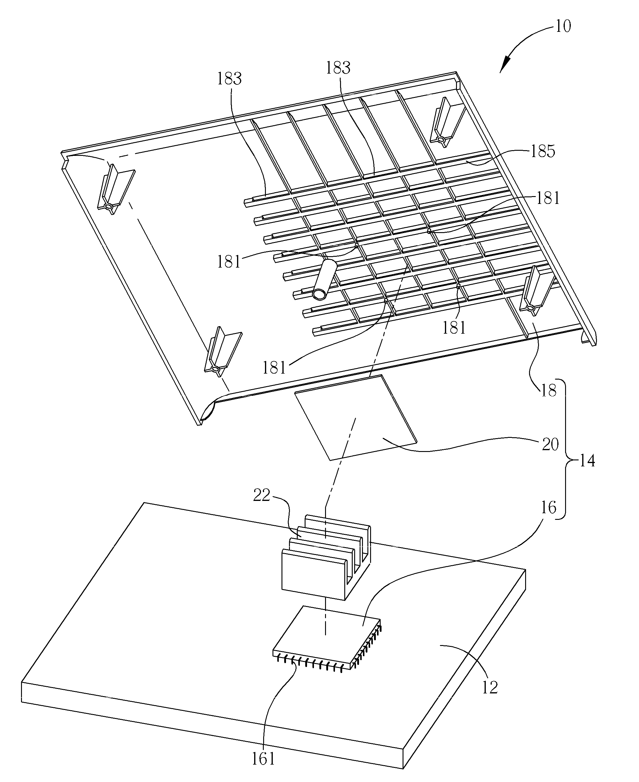
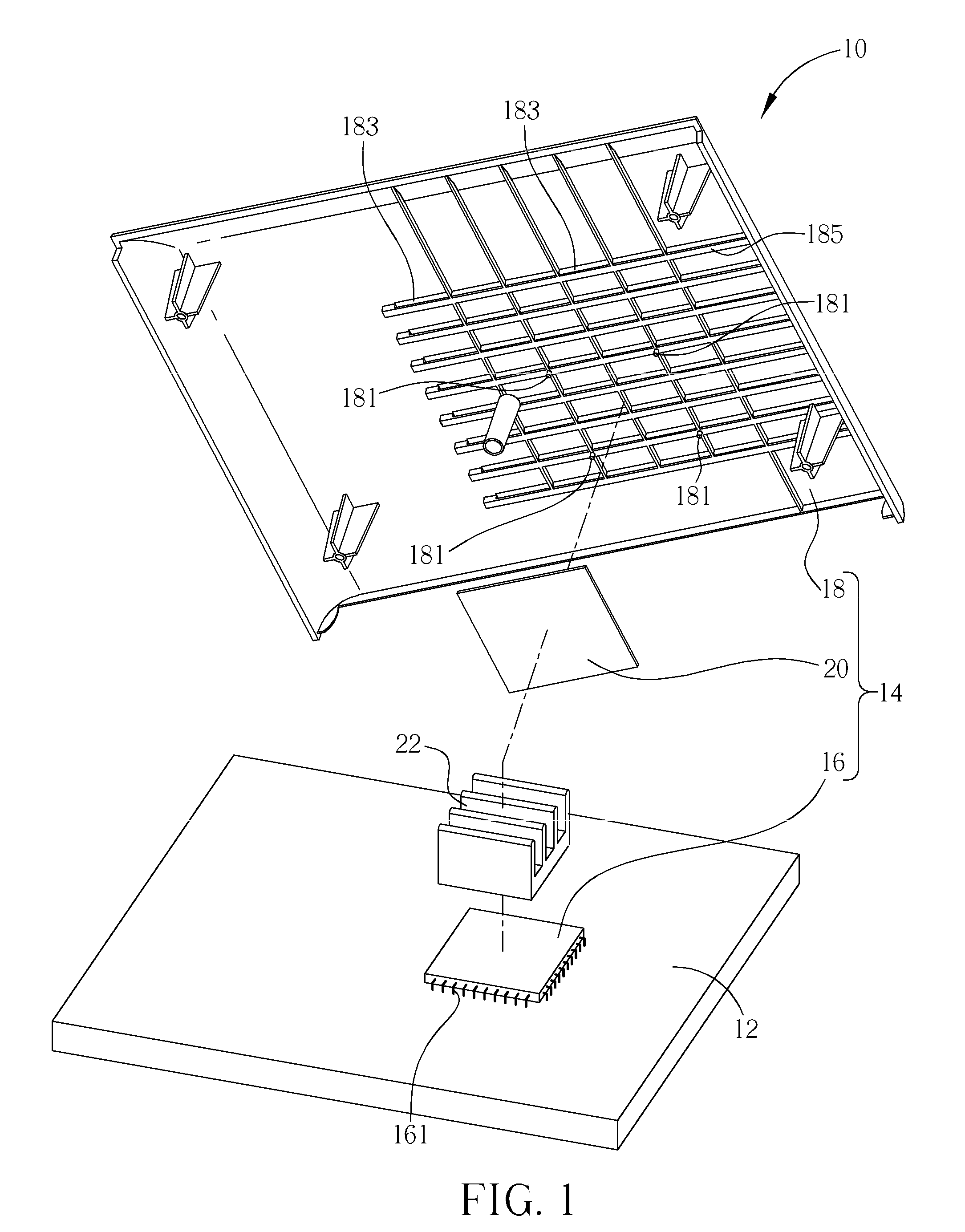
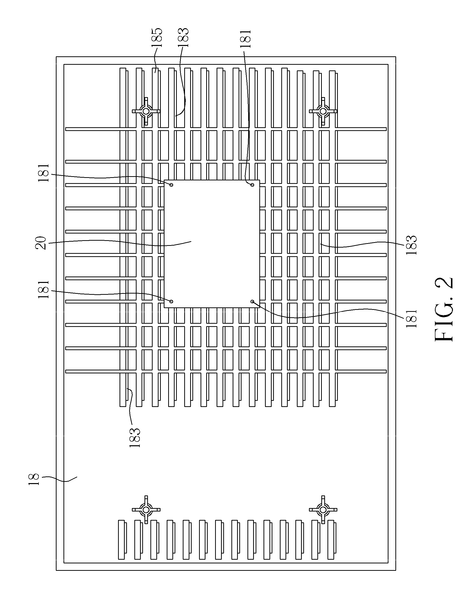
[0006]According to the claimed invention, an electronic device includes a circuit board, and a heat insulating structure. The heat insulating structure includes a heat source disposed on the circuit board, an enclosure for covering the circuit board and the heat source...

Problems solved by technology

Heat generated by the heat sources affects operational stability of the electronic device easily.
The plastic enclosure has low heat dissipating efficiency so that the heat generated by the heat sources and transmitting toward the enclosure directly warms the enclosure u...

Method used


Image

  • Electronic device with a heat insulating structure
  • Electronic device with a heat insulating structure
  • Electronic device with a heat insulating structure

Examples


second embodiment

[0017]Please refer to FIG. 4. FIG. 4 is a diagram of the electronic device 10 according to the present invention. In above embodiments, components have the same numerals as the above-mentioned embodiment have the same structures and functions and the detail description is omitted herein for simplicity. As shown in FIG. 4, the heat insulating structure 14 can further include a thermal conductive layer 24 disposed on a side of the heat insulating plate 20 facing to the heat source 16 for improving heat dissipating efficiency of the heat insulating plate 20. The thermal conductive layer 24 can be made of metal material or graphite material having preferred heat conductivity, such as copper, alumni and so on. Shape of the thermal conductive layer 24 is designed according to mechanical demand, such as a membrane or a mesh, and corresponding dimensions of the thermal conductive layer 24 and the heat insulating 20 are designed according to the actual demand. In addition, part of the enclos...

third embodiment

[0018]Please refer to FIG. 5. FIG. 5 is a diagram of the electronic device 10 according to the present invention. The heat insulating structure 14 can further include the thermal conductive layer 24 disposed on a side of the heat insulating plate 20 facing to the enclosure 18 for improving the heat dissipating efficiency of the heat insulating plate 20. Because pins 161 of the heat source 16 (not be shown in FIG. 5) mounted on the circuit board 12 might pierce through a side of the circuit board 12 opposite to the other side of the circuit board 12 whereon the heat source 16 disposed, the heat insulating plate 20 can be further utilized for insulating electrical connection of the circuit board 12 and the thermal conductive layer 24. The thermal conductive layer 24 can be made of metal material having preferred heat conductivity, such as copper, alumni and so on. Shape of the thermal conductive layer 24 is designed according to mechanical demand, such as a membrane or a mesh, and the...


PUM


Abstract

An electronic device includes a circuit board and a heat insulating structure. The heat insulating structure includes a heat source, an enclosure for covering the heat source, and a heat insulating plate disposed on a side of the enclosure facing to the heat source for preventing heat generated by the heat source from directly transmitting toward the enclosure, and a space being formed between the heat insulating plate and the enclosure. The heat insulating structure further includes a thermal conductive layer disposed on a side of the heat insulating plate facing to the heat source. The heat insulating structure further includes the thermal conductive layer disposed on a side of the heat insulating plate facing to the enclosure. Therefore, the heat insulating plate can be for altering heat current generated by the heat source so as to dissipate the heat current via holes on the enclosure uniformly.

Description

BACKGROUND OF THE INVENTION[0001]1. Field of the Invention[0002]The present invention relates to an electronic device, and more particularly, to an electronic device with a heat insulating structure capable of preventing heat from directly transmitting toward an enclosure.[0003]2. Description of the Prior Art[0004]With the advanced technology, a consumer electronic device includes several heat sources, such as a CPU (Central Processing Unit or SoC (System on Chip) or Power IC or a chip. Heat generated by the heat sources affects operational stability of the electronic device easily. Therefore, kinds of components are designed for dissipating the heat generated by the heat sources, such as a heat sink or a fan. Most enclosures of the electronic device can be made of plastic material. The plastic enclosure has low heat dissipating efficiency so that the heat generated by the heat sources and transmitting toward the enclosure directly warms the enclosure up violently. If temperature of...

Claims


Application Information

Patent Timeline
IPC IPC(8): H05K7/20
CPCH05K5/0213H05K5/0209
Inventor LIN, LI-TANGHSIEH, MING-CHENG
Owner GEMTEK TECH CO LTD
Why Eureka
Try Eureka