Clock recovery circuit and data recovery circuit

a clock recovery circuit and clock jitter technology, applied in the direction of digital transmission, pulse automatic control, electrical apparatus, etc., can solve the problems of high-level emi noise, increase of clock jitter, and increase of the transmission rate of high-speed serial data transmission

Inactive Publication Date: 2011-03-17
KK TOSHIBA
View PDF7 Cites 35 Cited by
  • Summary
  • Abstract
  • Description
  • Claims
  • Application Information

AI Technical Summary

Benefits of technology

[0015]An aspect of the present invention provides a clock recovery circuit for recovering clock signal based on inputted serial signal, which includes a plurality of samplers configured to sample a serial input signal in synchronization with a plurality of first clock signals having different phases respectively and to output a plurality of sampling data pieces, a phase comparison circuit configured to output a serial phase information signal on the basis of the sampling data pieces, the serial phase information signal representing a phase relationship between a clock of the serial input signal and the different phases of the first clock signals, a serial-parallel conversion circuit configured to perform a serial-to-parallel conversion on the serial phase information signal in synchronization with a second clock signal having a frequency lower than that of the first clock signals, and to output a parallel phase information signal, a digital filtering circuit configured to calculate a phase deviation signal and a phase advance-delay signal on the basis of the parallel phase information signal, in synchronization with the second clock signal, a phase control amount processing circuit configured to generate a phase control signal on the basis of the phase deviation signal and the phase advance-delay signal and to output the phase control signal, the phase control signal being in synchronization with third clock signals having a frequency higher than that of the second clock signal, and a phase interpolation circuit configured to adjust the phases of the third clock signals on the basis of the phase control signal, and to output the first clock signals as recovery clock signals.
[0016]Another aspect of the present invention provides a data recovery circuit for recovering clock signal based on inputted ...

Problems solved by technology

A signal used for a high-speed serial data transmission includes high-level EMI noise.
It causes increase in clock jitters, with incr...

Method used


Image

  • Clock recovery circuit and data recovery circuit
  • Clock recovery circuit and data recovery circuit
  • Clock recovery circuit and data recovery circuit

Examples


Embodiment Construction

[0033]Hereinafter, a clock recovery circuit and a data recovery circuit, according to embodiments of the invention, will be described in detail with reference to the accompanying drawings. In the drawings, the same reference symbols designate the same or similar portions respectively.

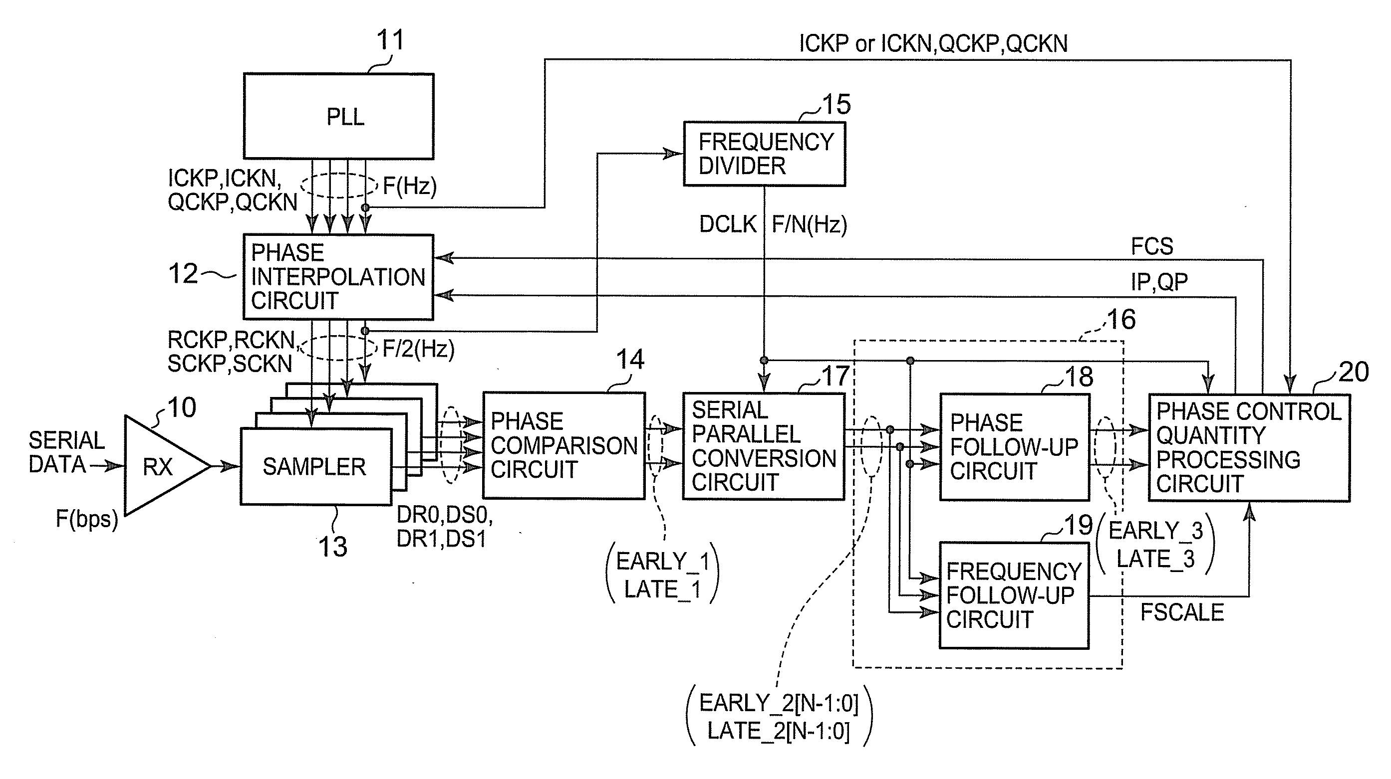
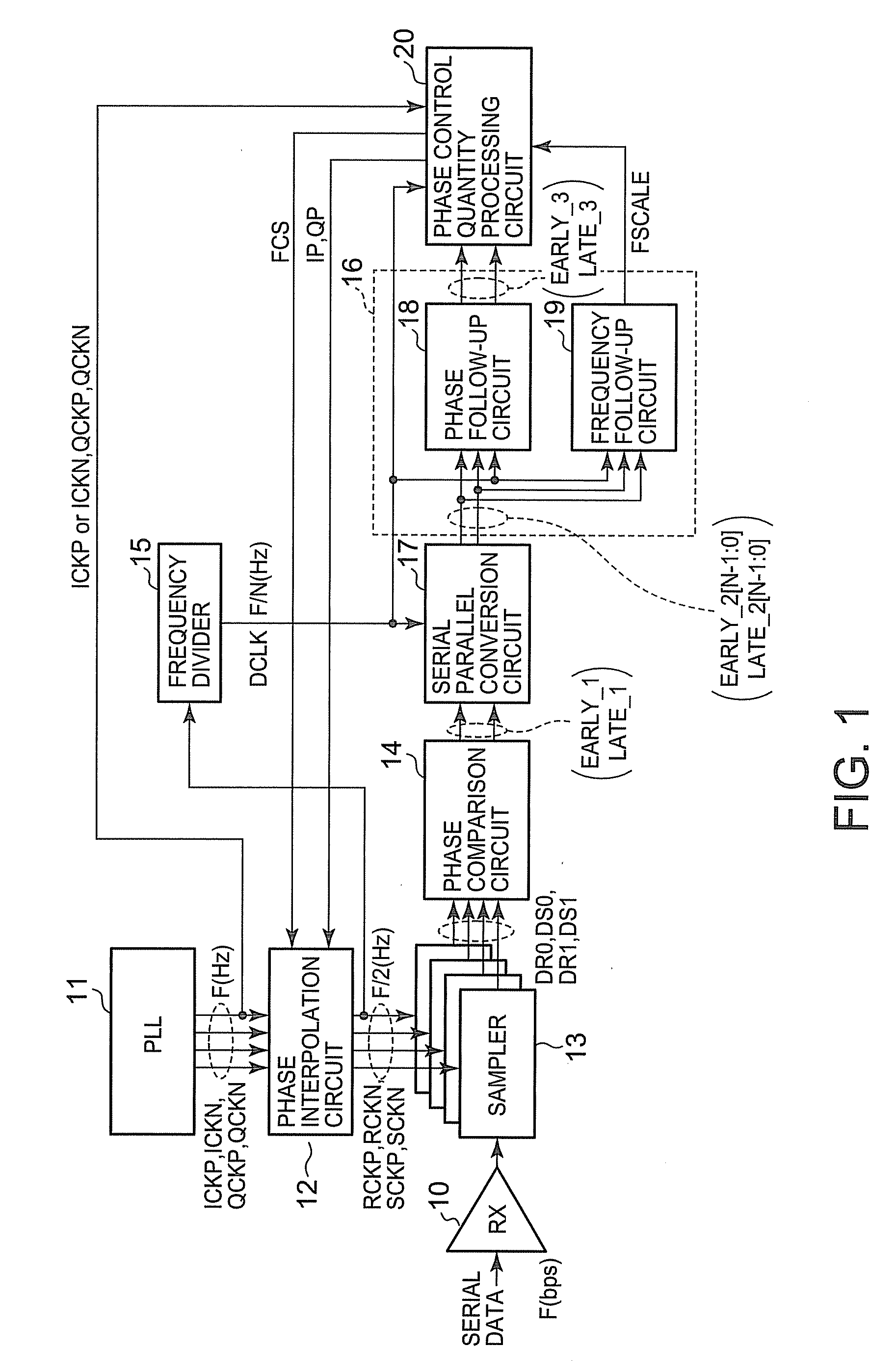
[0034]FIG. 1 is a block diagram showing a configuration of the clock recovery circuit. The clock recovery circuit may be arranged in a receiver. As shown in FIG. 1, the clock recovery circuit is provided with a receiving circuit 10, a PLL (Phase-Locked Loop) circuit 11, a phase interpolation circuit 12, four samplers 13, a phase comparison circuit 14, a frequency divider circuit 15, a serial / parallel conversion circuit 17, a phase tracking circuit 18, a frequency tracking circuit 19, and a phase control amount processing circuit 20.

[0035]The phase tracking circuit 18 and the frequency tracking circuit 19 form a digital filtering circuit 16 which is shown by a dashed line in FIG. 1. The digital filtering...


PUM


Abstract

A serial input signal is sampled in synchronization with a plurality of first clock signals to obtain a plurality of sampling data pieces. A phase comparison circuit outputs a serial phase information signal based on the sampling data pieces. A serial-parallel conversion circuit performs a serial-to-parallel conversion on the serial phase information signal in synchronization with a second clock signal having a lower frequency, to output a parallel phase information signal. A digital filtering circuit calculates phase deviation and phase advance-delay signals based on the parallel phase information signal in synchronization with the second clock signal. By these signals, a phase control amount processing circuit generates a phase control signal. The phase control signal is in synchronization with third clock signals having a higher frequency. A phase interpolation circuit adjusts the phases of the third clock signals based on the phase control signal to output the first clock signals.

Description

CROSS REFERENCE TO RELATED APPLICATION[0001]This application is based upon and claims the benefit of priority from the prior Japanese Patent Application No. 2009-212290, filed on Sep. 14, 2009, the entire contents of which are incorporated herein by reference.FIELD OF THE INVENTION[0002]The invention relates to a clock recovery circuit which recovers a clock signal from a received signal, and to a data recovery circuit which recovers a data signal by using a recovered clock signal.DESCRIPTION OF THE BACKGROUND[0003]In many gigahertz-class high-speed data transmissions, a transmitter converts parallel data into serial data and transmit the converted serial data to a receiver by a serial transmission. The receiver receives the transmitted serial data and converts it into parallel data.[0004]In a usual receiver used in such high-speed serial data transmissions, serial data are sampled using a clock signal recovered from serial data. Further, data of the serial data are received and rec...

Claims


Application Information

Patent Timeline
IPC IPC(8): H04L7/00
CPCH03L7/07H03L7/0807H04L7/0337H03L7/091H03L7/0814
Inventor TAKADA, SHUICHI
Owner KK TOSHIBA
Why Eureka
Try Eureka