Roller bearing backing ring

a backing ring and roller bearing technology, applied in the direction of bearing rigid support, mechanical equipment, transportation and packaging, etc., can solve the problems of reducing the rigidity of the non-fitted backing ring in comparison to the fitted backing ring, the non-fitted backing ring often experiences fretting wear, shaft or bearing failure, etc., to reduce the potential for fretting wear, increase stability, and reduce the effect of fretting wear

Active Publication Date: 2011-03-17
AMSTED RAIL CO INC
View PDF3 Cites 18 Cited by
  • Summary
  • Abstract
  • Description
  • Claims
  • Application Information

AI Technical Summary

Benefits of technology

[0008]To reduce the potential for fretting wear on journals and backing rings, a novel backing ring assembly is presented having increased stability to reduce fretting wear. The novel backing ring assembly is composed of two components: (1) an annular body affixed to the fillet of the journal and (2) a locking ring to connect with and further affix the annular body on the journal. The locking ring has an outboard end engaging the annular body and an inboard end affixed to the outer diameter of the dust guard. The locking ring reduces axial movement in the annular body resulting from shaft and journal deflection.

Problems solved by technology

As result of shaft deflections, the backing ring and the journal often experience fretting wear as the backing ring moves relative to the journal.
The loose backing ring accelerates wear on the bearing assembly and journal, potentially leading to shaft or bearing failure.
This substantially reduces the rigidity of the non-fitted backing ring in comparison to the fitted backing ring.
As a result, prior generation railcar axle assemblies have higher wear rates than the current generation.
Consequently, certain advantages of fitted backing rings are not realized when used to recondition bearings on prior generation railcar axles.

Method used


Image

  • Roller bearing backing ring
  • Roller bearing backing ring
  • Roller bearing backing ring

Examples


Embodiment Construction

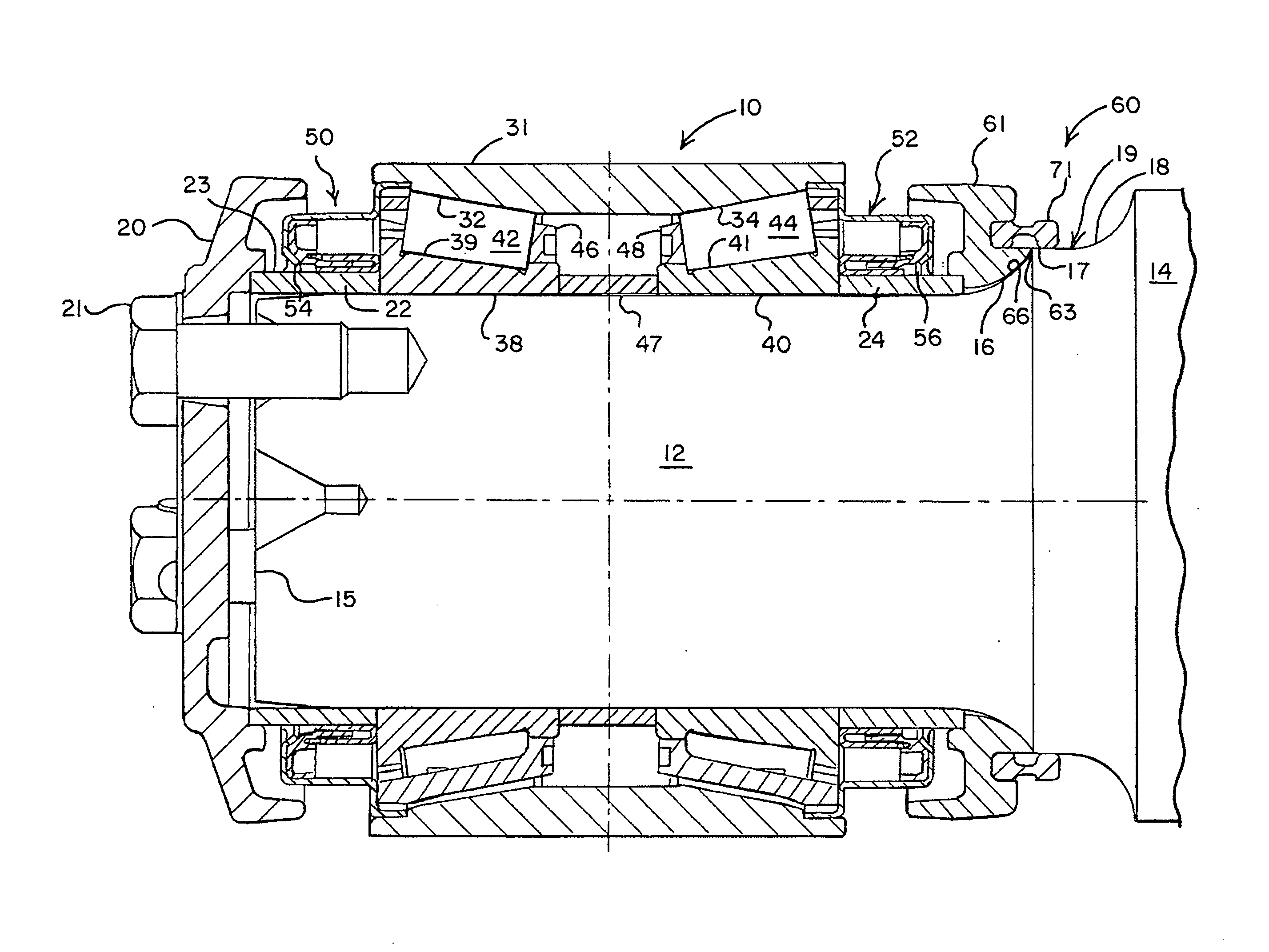
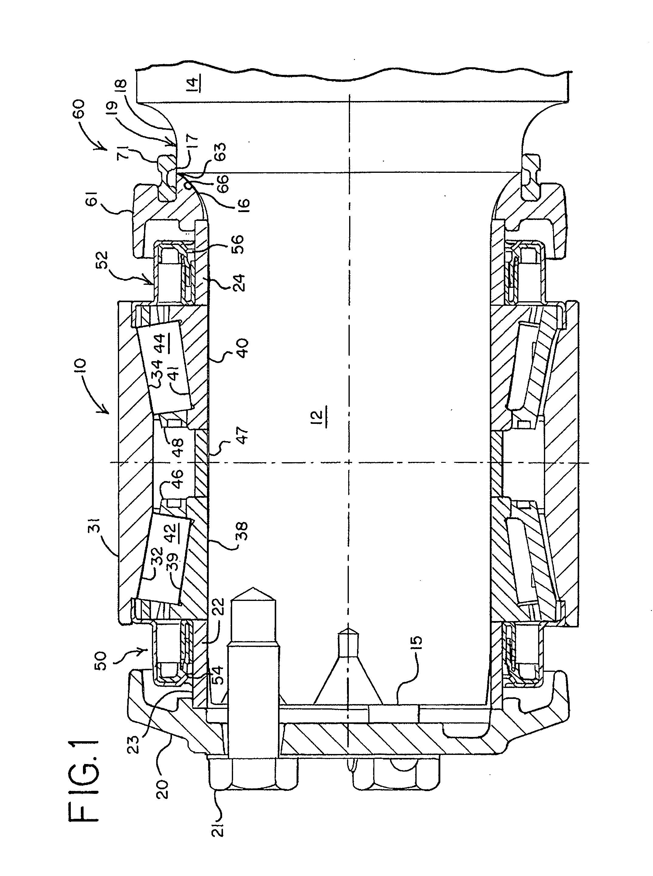
[0016]Referring to FIG. 1, one embodiment of the backing ring assembly is illustrated. In this embodiment, the bearing assembly 10 is a tapered roller bearing of the type commonly used in railway applications to support a railcar wheel. The bearing assembly 10 described in the following embodiments, however, may be adapted for use in many other common industrial applications. Consequently, the bearing assembly 10 illustrated and described below in relation to a tapered roller bearing assembly for a railcar wheel is for convenience only.

[0017]The bearing assembly 10 is typically preassembled before being mounted on a shaft 14 (e.g., a railcar axle). At each free end of the shaft 14, a journal 12 terminates in a slightly conical tapered section 15 to facilitate installation of the bearing assembly 10 onto the journal. The bearing assembly 10 is pressed onto the journal 12 of the shaft 14 to establish an interference fit.

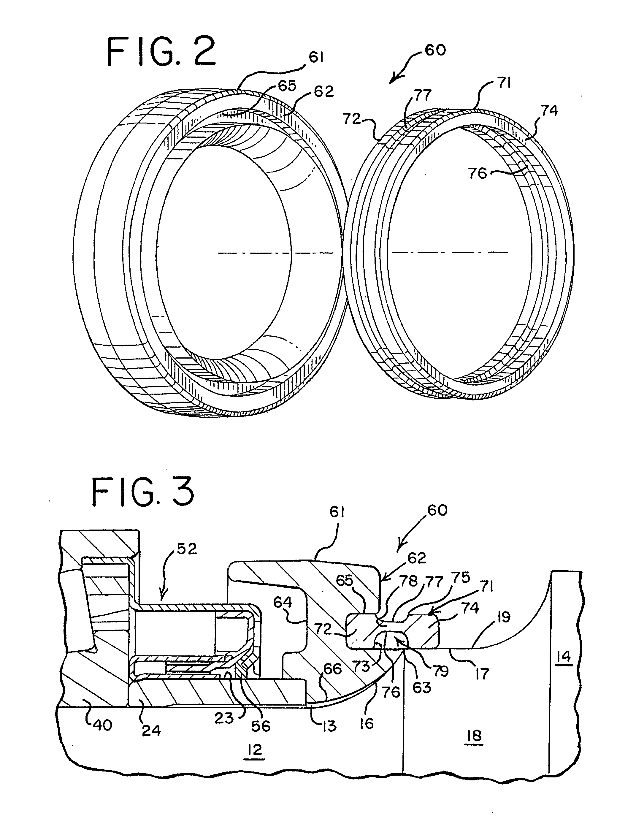
[0018]A dust guard 18 with a larger diameter than the journal 12 ...


PUM


Abstract

A novel two-piece backing ring assembly for a railcar axle is presented. The backing ring assembly has an annular body affixed to the fillet of the journal and a locking ring for further affixing the annular body into position on the journal. The locking ring has an inboard end affixed to the dust guard of the shaft and an outboard end for engaging a slot in the annular body. The locking ring assembly may be retrofitted to older generation railcar axles to increase the structural rigidity of the bearing assembly and minimize fretting wear caused by railcar axle deflection.

Description

FIELD OF THE INVENTION[0001]This invention relates to anti-friction bearings, and more particularly, in one embodiment, to the backing rings used with tapered roller bearings on railcar axles.BACKGROUND OF THE INVENTION[0002]Tapered roller bearings on railcar axles support operating loads capable of producing significant flexural deflections in the axle, and in particular, the journal portion of the shaft on which the tapered roller bearing is affixed. The stresses imposed by the operating loads are particularly high in the journal portion of the shaft at or near the backing ring.[0003]As result of shaft deflections, the backing ring and the journal often experience fretting wear as the backing ring moves relative to the journal. Fretting wear may be sufficient to loosen the backing ring, increasing the axial play of the bearing on the journal. The loose backing ring accelerates wear on the bearing assembly and journal, potentially leading to shaft or bearing failure.[0004]In an eff...

Claims


Application Information

Patent Timeline
Patent Type & Authority Applications(United States)
IPC IPC(8): F16C33/58
CPCF16C35/063F16C2326/10B61F15/22F16C19/386
Inventor HUBBARD, PAUL A.FETTY, MARK W. K.OLIVER, JOHN
Owner AMSTED RAIL CO INC
Why Eureka
Try Eureka