Secondary Inlet Cone for a Plenum Fan

a technology of plenum fans and inlet cones, which is applied in the direction of machines/engines, stators, liquid fuel engines, etc., can solve the problems of affecting the alignment of the inlet cone, the relatively large side panels of the enclosure can emit appreciable noise, and the inlet cone's relatively large side panels can be difficult to maintain, so as to prevent vibration transmission, tight radial clearance, and the effect of reducing the number of inlet cones

Active Publication Date: 2011-03-17
TRANE INT INC
View PDF10 Cites 13 Cited by
  • Summary
  • Abstract
  • Description
  • Claims
  • Application Information

AI Technical Summary

Benefits of technology

[0009]Another object of some embodiments is to isolate the vibration of a fan assembly from an outer enclosure while maintaining a smooth inlet to the fan.
[0010]Another object of some embodiments is to provide a plenum fan with relatively tight radial clearance between a fan wheel mouth and an adjacent primary inlet cone and to provide greater radial clearance between the adjacent primary inlet cone and a secondary inlet cone.
[0011]One or more of these and/or other objects of the invention are provided by a plenum fan that includes a fan wheel disposed within an enclosure. A flexible duct couples a primary inlet cone to a side panel of the enclosure, wherein the suction duct's flexibility prevents transmission of vibration from the primary inlet cone to the enclosure. A secondary inlet cone attached to the enclosure protrudes into, or at least toward, the primary inlet cone and covers the irregular surface of the flexible duct, thereby providing a smooth inlet flow path to the fan wheel.
[0012]The present invention provides a plenum fan for moving air. The plenum fan comprises an enclosure defining an inlet opening, an outlet and a plenum. A frame is disposed within the enclosure. The plenum fan also comprises a fan wheel defining a fan mouth. The fan wheel is supported by the frame within the enclosure. The fan wheel is rotatable to force air sequentially through the inlet opening, through the fan mouth, through the plenum, and out through the outlet. The plenum fan also comprises a secondary inlet cone attached to the enclosure and protruding into the inlet opening, wherein the secondary inlet cone is substantially stationary relative to the enclosure. The plenum fan also comprises a primary inlet cone attached to the frame such that the primary inlet cone is substantially stationary relative to the frame, and air being drawn into the enclosure by the fan wheel passes sequentially through the secondary inlet cone, through the primary inlet cone and through the mouth of the fan wheel. The plenum fan also comprises a flexible duct extending between the primary inlet cone and the enclosure. The flexible duct is more flexible than the secondary inlet cone and the primary inlet cone, wherein the flexibility of the flexible duct permits relative movement between the primary inlet cone and the enclosure and also permits relative movement between the primary inlet cone and the secondary inlet cone.
[0013]The present invention also provides a plenum fan for moving air. The plenum fan comprises an enclosure defining an inlet opening, a outlet and a plenum. The plenum fan also comprises a frame disposed within the enclosure. The plenum fan also comprises a fan wheel defining a fan mouth and being supported by the frame within the enclosure. The fan wheel is rotatable to force air sequentially through the inlet opening, through the fan mouth, through the plenum, and out through the outlet. The plenum fan also comprises a secondary

Problems solved by technology

Such alignment can be difficult to maintain if the fan wheel vibrates or otherwise translates relative to the inlet cone.
If the vibration transmits to the enclosure of a plenum fan, the enclosure's relatively large side panels might emit

Method used


Image

  • Secondary Inlet Cone for a Plenum Fan
  • Secondary Inlet Cone for a Plenum Fan
  • Secondary Inlet Cone for a Plenum Fan

Examples


Embodiment Construction

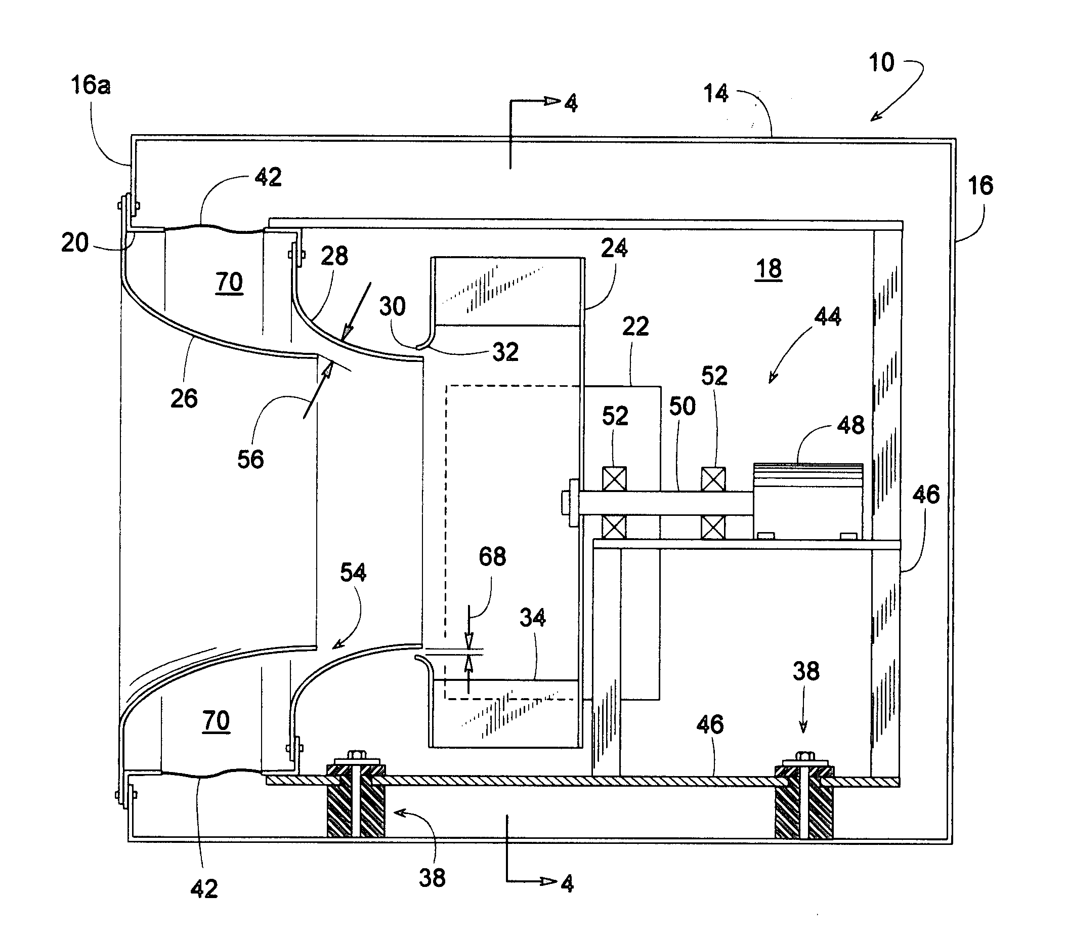
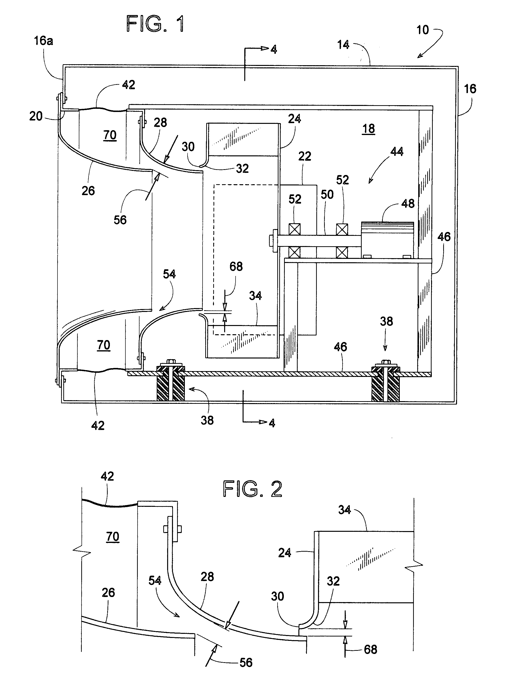
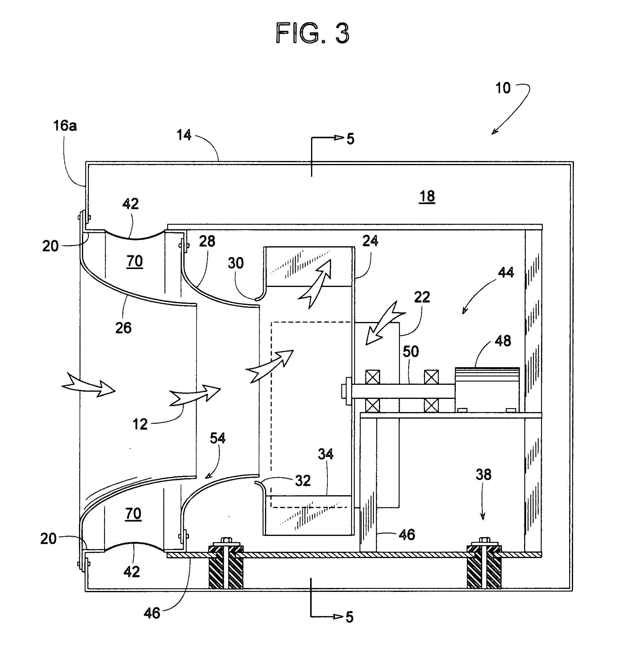
[0020]FIGS. 1-5 illustrate a plenum fan 10 that forces air 12 through a box-like enclosure 14 comprising a plurality of sheet metal side panels 16 that define a plenum 18 in fluid communication with an inlet opening 20 and an outlet 22. A fan wheel 24 (e.g., a centrifugal fan wheel, vane axial fan wheel, etc.) rotating within plenum 18 draws air 12 into enclosure 14 through inlet opening 20. Air 12 flows sequentially through a secondary inlet cone 26, a primary inlet cone 28, and a fan mouth 30 of fan wheel 24. Inlet cones 26 and 28 are smoothly curved funnels that minimize airflow pressure losses. Inlet cones 26 and 28 can be formed of sheet metal or some other relatively rigid material. To further minimize losses, fan wheel 24 preferably has a curved rim 32 at fan mouth 30. Upon entering fan wheel 24, a plurality of fan blades 34 then forces air 12 through plenum 18 and out through outlet 22. An air duct 36 at outlet 22 can be used for conveying air 12 to a comfort zone or to wher...


PUM


Abstract

A plenum fan comprising a fan wheel disposed within a box-like enclosure includes a secondary inlet cone, a primary inlet cone, and a flexible duct. The two inlet cones convey air to the mouth of the fan wheel. A frame supports the fan wheel and the primary inlet cone such that the frame, the fan wheel and the primary inlet cone comprise a fan assembly. If the fan assembly shifts due to fan thrust or vibration, the fan assembly moves as a unit. The flexible duct connects the primary inlet cone to an inlet of the enclosure while isolating the fan assembly's vibration from the enclosure. The secondary inlet cone extends from the inlet of the enclosure, protrudes into or toward the primary inlet cone and provides a smooth airflow path over the abrupt shape of the flexible duct.

Description

BACKGROUND OF THE INVENTION[0001]1. Field of the Invention[0002]The subject invention generally pertains to plenum fans and more specifically to an inlet cone arrangement for such a fan.[0003]2. Description of Related Art[0004]A typical plenum fan comprises a fan wheel inside a plenum of a box-like enclosure. Upon drawing air into the enclosure through an inlet, the fan wheel pressurizes the air in the plenum. An outlet in the enclosure releases the pressurized air to perhaps a supply air duct, which can convey the air to a comfort zone or to wherever the air is needed.[0005]To promote smooth inlet airflow, many fans include some type of inlet cone. Examples of various inlet cones are disclosed in U.S. Pat. Nos. 2,798,658; 2,798,659; 3,070,287; 3,278,115; 5,525,036 and 5,551,838. For efficient operation, it usually helps to align such inlet cones accurately to the inlet mouth of the fan wheel. Such alignment can be difficult to maintain if the fan wheel vibrates or otherwise transla...

Claims


Application Information

Patent Timeline
IPC IPC(8): F04D29/44
CPCF04D29/441F04D29/4213F05D2250/51
Inventor LIND, STEPHEN J.LEY, THOMAS A.MEREDITH, DUSTIN E.J.
Owner TRANE INT INC
Why Eureka
Try Eureka