Cooling device

Inactive Publication Date: 2011-03-17
MURATA MFG CO LTD
View PDF3 Cites 28 Cited by
  • Summary
  • Abstract
  • Description
  • Claims
  • Application Information

AI Technical Summary

Benefits of technology

[0034]With preferred embodiments of the present invention, the amplitude is increased, and the cooling capability is im

Problems solved by technology

Therefore, a temperature distribution of a space between the heat dissipating fins is not uniform, and a high-temperature portion is concentrated in the vicinity of the walls of the heat dissipating fins.
That is, causing air to flow al

Method used


Image

  • Cooling device
  • Cooling device
  • Cooling device

Examples


first preferred embodiment

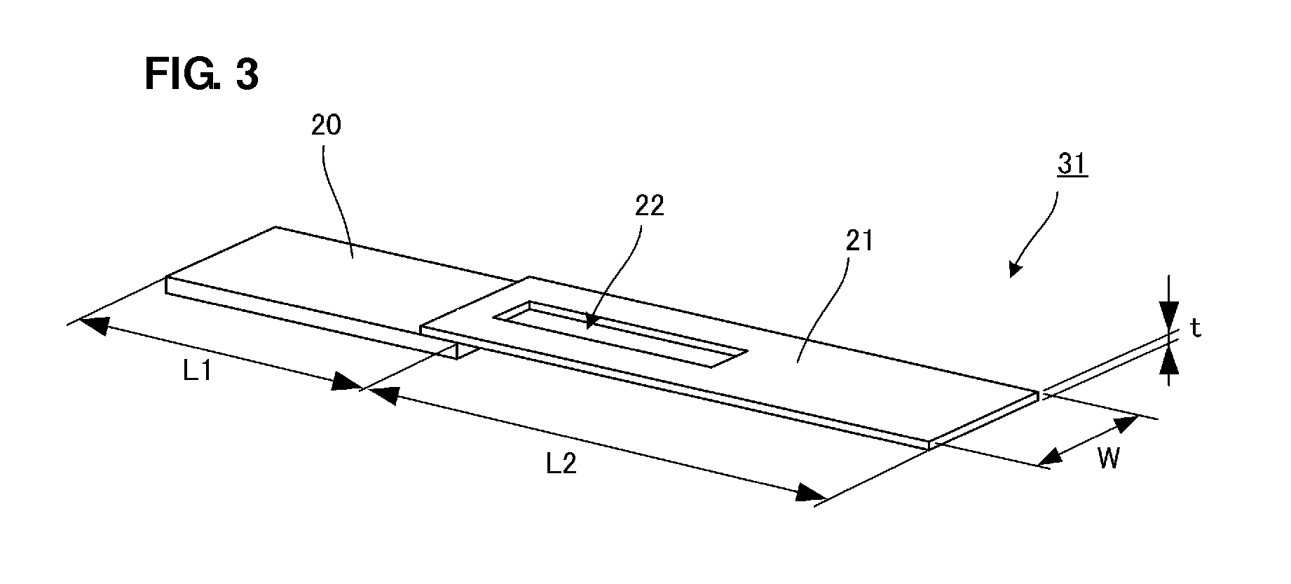
[0057]FIG. 3 is a perspective view of a piezoelectric fan for use in a cooling device according to a first preferred embodiment of the present invention. In FIG. 3, a piezoelectric fan 31 includes a blade 21 and a piezoelectric oscillator 20. The blade 21 includes a hole 22. The piezoelectric oscillator is preferably a bimorph piezoelectric oscillator in which a piezoelectric element is arranged on each of two opposed surfaces of a metal plate defining intermediate electrode. That is, each of the piezoelectric elements on both surfaces of the metal plate defining the intermediate electrode of the piezoelectric oscillator 20 includes an electrode film provided on its surface, and polarization is performed such that each of the piezoelectric elements is caused to oscillate by being bent in the longitudinal direction (L1 dimension direction) by the application of a driving voltage corresponding to a polarization direction of the piezoelectric element to the electrode and the metal plat...

second preferred embodiment

[0081]In the first preferred embodiment, the blade 21 includes the single hole 22 extending along the longitudinal direction of the blade. FIGS. 8A and 8B illustrate two configurations of a piezoelectric fan that are different from that of the first preferred embodiment.

[0082]The example shown in FIG. 8A illustrates a piezoelectric fan 32 in which the blade 21 preferably includes a cut 23 extending along the longitudinal direction of the blade 21 at an end thereof (farther from the piezoelectric oscillator 20). In the structure illustrated in FIG. 8A, the hole is arranged at the end of the blade 21. As described above, when the cut 23 is disposed at the end of the blade 21, the effect of increasing the amplitude of the blade 21 resulting from a reduction in air resistance and the effect of sweeping high-temperature air on the walls of the heat dissipating fins are obtained.

[0083]In the example shown in FIG. 8B, a piezoelectric fan is configured such that the blade 21 having a plural...

third preferred embodiment

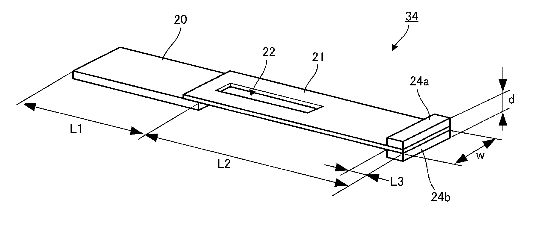
[0090]FIG. 9 is a perspective view of a piezoelectric fan for use in a cooling device according to a third preferred embodiment of the present invention. In this example, the blade 21 including the hole 22 and weights 24a and 24b disposed at the end and the piezoelectric oscillator 20 define a piezoelectric fan 34.

[0091]The weights 24a and 24b are preferably made of the same or substantially the same stainless steel as the blade 21 and are joined thereto by adhesive, for example. The dimensions L3 and d of the weights 24a and 24b illustrated in the drawing are preferably about 2 mm and about 0.5 mm, respectively, for example. The thickness dimension of the blade 21 preferably is about 100 μm, for example. The other dimensions L1, L2, and W are the same or substantially the same as in the first preferred embodiment illustrated in FIG. 3: L1=about 12 mm, L2=about mm, and W=about 6 mm, for example. The location and dimensions of the hole 22 are the same or substantially the same as in ...


PUM


Abstract

A piezoelectric fan includes a blade that is joined to a piezoelectric oscillator that bends in response to an application of a voltage, and the blade of the piezoelectric fan is arranged to swing in a space between neighboring heat dissipating fins of a heat sink. The formation of a hole in the blade increases the amplitude of the blade and also improves the sweep effect of sweeping high-temperature air in the vicinity of the wall of the heat dissipating fin, and thus, improves the cooling capability of the piezoelectric fan.

Description

BACKGROUND OF THE INVENTION[0001]1. Field of the Invention[0002]The present invention relates to a cooling device for ejecting heat from the inside of an electronic apparatus to the outside thereof, the cooling device using a piezoelectric fan.[0003]2. Description of the Related Art[0004]Recently, for a portable electronic apparatus, in particular, with the advancement of miniaturization and high-density mounting, devices for reducing heat inside the electronic apparatus are desired.[0005]One example of a portable electronic apparatus in which the above issue is especially important is a portable personal computer. For portable personal computers, both miniaturization and increased central processing unit (CPU) speeds that improve performance of information processing are advancing. As a result, high-density mounting of parts deteriorates the ventilation inside an electronic apparatus, while heat generated by a CPU increases. This makes it more difficult to dissipate the heat to the...

Claims


Application Information

Patent Timeline
IPC IPC(8): F04B17/03
CPCG06F1/20H01L23/467H05K7/20172F04D33/00H01L2924/0002H01L2924/00
Inventor WADA, HIROAKIKAMITANI, GAKU
Owner MURATA MFG CO LTD
Why Eureka
Try Eureka