Method and apparatus for performing MPEG video streaming over bandwidth constrained networks

a bandwidth-constrained network and video streaming technology, applied in the field of video encoding and transmission of encoded video signals, can solve the problems of network bottlenecks and insufficient quality for users receiving video, and achieve the effect of increasing the minimum reserved bandwidth

Inactive Publication Date: 2011-03-17
ALCATEL-LUCENT USA INC
View PDF12 Cites 14 Cited by
  • Summary
  • Abstract
  • Description
  • Claims
  • Application Information

AI Technical Summary

Benefits of technology

[0005]We have recognized that, given the inherent bandwidth limitations of many communications networks such as, for example, wireless networks, and given the capability of today's communications networks such as, for example, WiMAX and LTE networks, to offer differing QoS levels to different traffic flows, it would be highly advantageous if a system could take advantage of such different QoS levels when transmitting a given video signal across the network. In particular, we note that a typical encoded video signal comprises a plurality of individual encoded video frames, and that various ones of these frames are encoded with use of different encoding formats. As such, we have further recognized that by decomposing an encoded video signal into a plurality of separate, independent video streams, and then transmitting these independent video streams as separate flows, each of these separate flows may, for example, be advantageously assigned different QoS levels such that those flows which comprise more “important” portions of the video signal can be transmitted with a higher minimum reserved bandwidth than those flows which comprise less “important” portions.

Problems solved by technology

But the substantial bandwidth requirements associated with video signal transmission often results in a network bottleneck, since the bandwidth available in typical wireless networks is relatively scarce.
As such, an encoded video signal, like other traffic flows, is typically transmitted in an assigned service class, which may or may not provide an adequate quality to the user receiving the video.

Method used


Image

  • Method and apparatus for performing MPEG video streaming over bandwidth constrained networks
  • Method and apparatus for performing MPEG video streaming over bandwidth constrained networks
  • Method and apparatus for performing MPEG video streaming over bandwidth constrained networks

Examples


Embodiment Construction

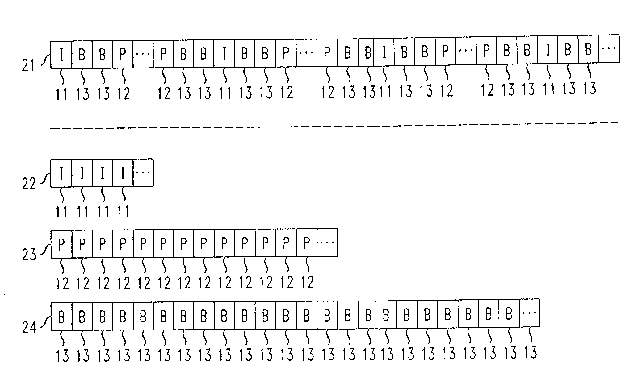
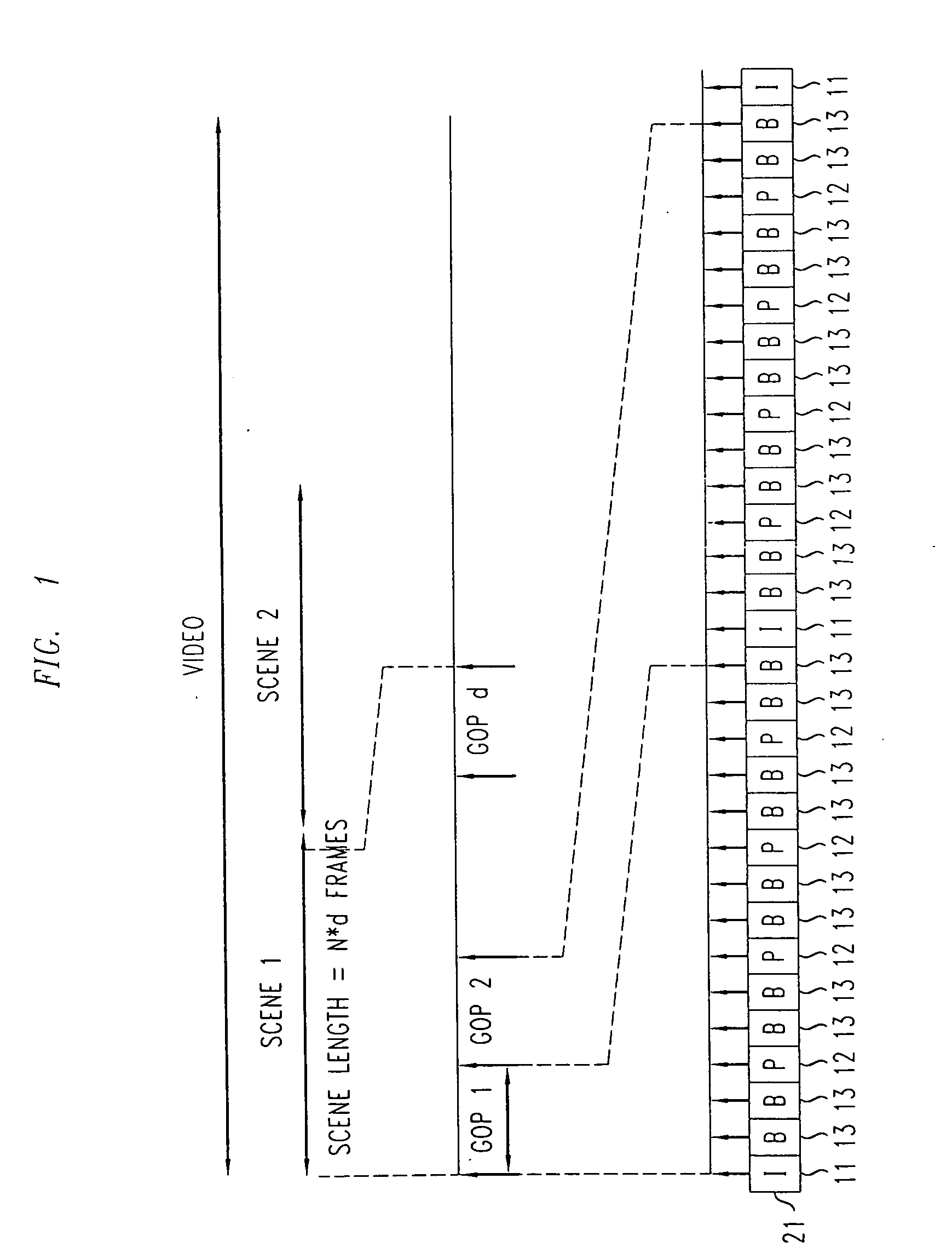
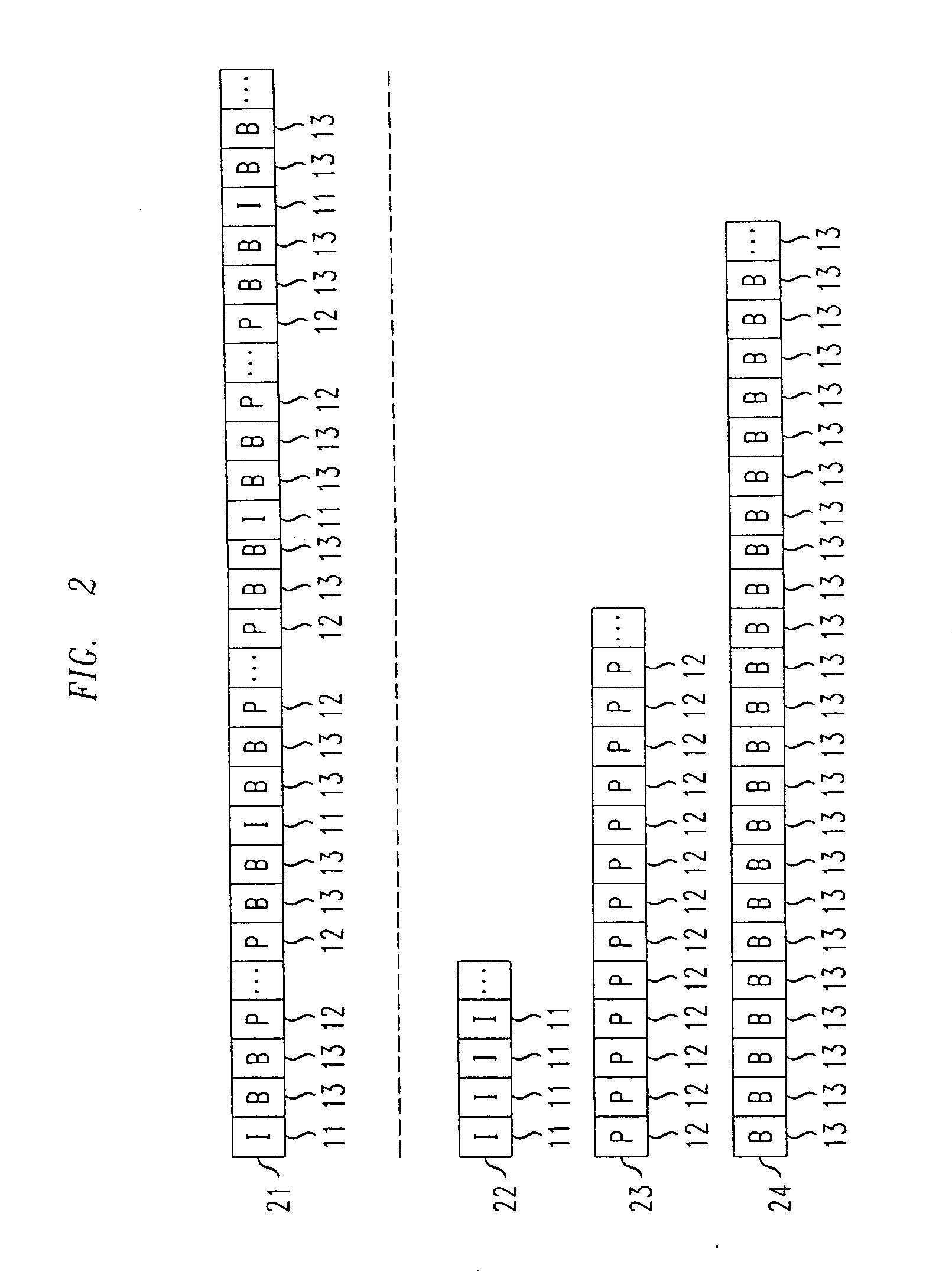
[0016]FIG. 1 shows an example of how a video signal may be advantageously encoded using a Motion Pictures Expert Group (MPEG) encoding technique for use with an illustrative embodiment of the present invention. MPEG encoding techniques are conventional and fully familiar to those of ordinary skill in the art. As is well known, a video signal comprises a sequence of frames, each of which comprises a (still) image, such that the sequence of images when displayed in real time produces the resultant video. In conventional video encoding techniques, each of these frames is encoded so as to reduce the quantity of data that must be used to represent it and thus, for example, to reduce the quantity of data which must be transmitted across a communications network.

[0017]In MPEG encoded video, there are typically three encoding formats which are advantageously employed to encode the frames of the video signal. These three formats comprise Intra-coded frames (I-frames), which encode the given ...


PUM


Abstract

A method and apparatus for preserving the video quality of encoded video signals when transmitted over a communications network. The video signals may comprise Motion Picture Experts Group (MPEG) encoded video signals and the communications network may comprise a WiMAX or an LTE network. Illustratively, an MPEG encoded video signal is decomposed into three component video streams made up of I-frames, P-frames and B-frames, respectively. The three video streams may then be independently transmitted as separate and independent flows with different Quality of Service (QoS) levels. For example, the video stream comprising I-frames may be assigned a highest QoS level, while the video stream comprising B-frames may be assigned a lowest QoS level (with the video stream comprising P-frames assigned a QoS level therebetween). A receiver at the receiving end receives the independently transmitted video streams and combines them together to reproduce the encoded video signal.

Description

RELATED APPLICATION[0001]The present application claims priority from U.S. Provisional Patent Application Ser. No. 61 / 276,588, filed on Sep. 14, 2009.FIELD OF THE INVENTION[0002]The present invention relates generally to the field of video encoding and transmission of encoded video signals, and more particularly to a method and apparatus for improving the quality of encoded video signals such as those encoded using an MPEG (Moving Picture Experts Group) encoding technique when such encoded video signals are transmitted over a congested network.BACKGROUND OF THE INVENTION[0003]The excessive demand for ubiquitous broadband access, particularly in a wireless context, has attracted tremendous investment from the telecommunications industry in the development and deployment of sophisticated communications networks such as, for example, Worldwide Interoperability for Microwave Access (WiMAX) networks and Long Term Evolution (LTE) of Universal Mobile Telecommunications System (UTMS) networ...

Claims


Application Information

Patent Timeline
Patent Type & Authority Applications(United States)
IPC IPC(8): H04N7/32H04N7/16G06F15/16
CPCH04N21/234327H04N21/2662H04N21/6131H04N19/577H04N19/37H04N19/31H04N19/159
Inventor PAREKH, SHYAMCALIN, DORUHAGHANI, EHSANKIM, EUNYOUNG
Owner ALCATEL-LUCENT USA INC
Why Eureka
Try Eureka