LEDs driven at higher levels of
forward current will degrade faster, and therefore have a shorter useful life, than the same LEDs driven at lower levels of
forward current.
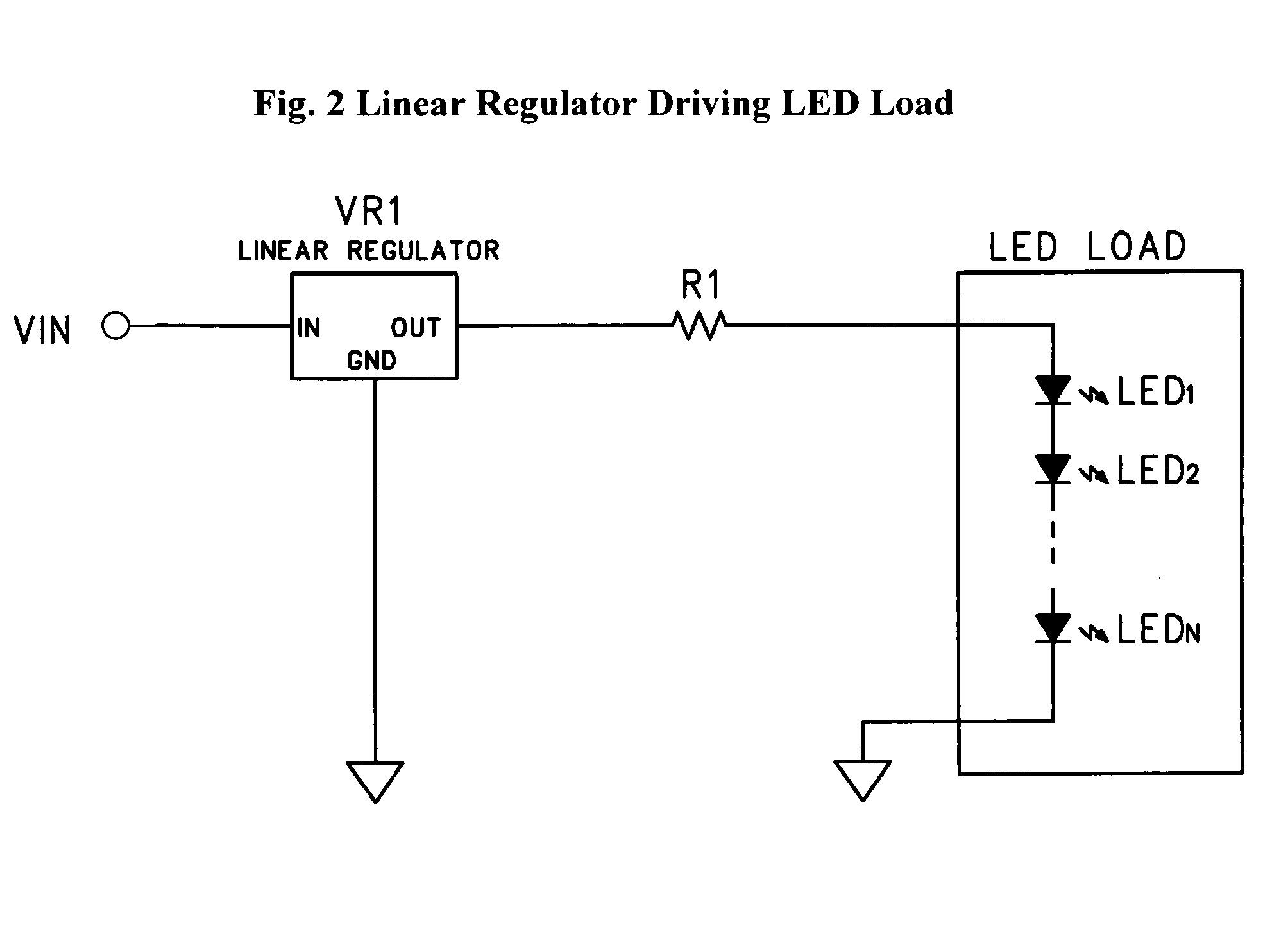
For this reason, linear regulators are not very efficient circuits when the input voltage is much larger than the required output voltage.
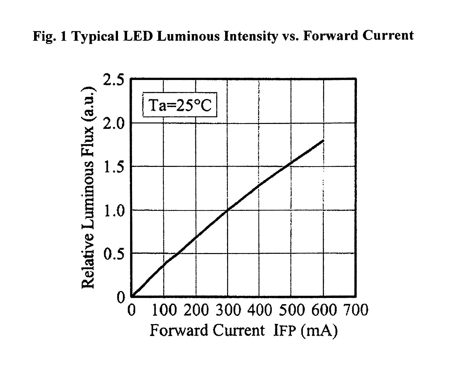
However, LEDs are not linear devices and small changes in voltage result in large changes in current which correspondingly effect large changes in output intensity.
The lower power efficiency of linear regulators makes them a poor choice in large power systems and in systems where the input voltage is much larger than the required LED driving voltage.
As such, these systems typically do not employ them.
Additionally, because of the requirement that the input voltage be higher than the output voltage in a
linear regulator, it is not a viable choice where a higher output than input voltage is needed such as a
low voltage source driving a series string of LEDs.
However the dimming is very non-linear and these regulators are inefficient.
An even greater problem with dimming switching
regulator drivers by lowering their input voltage is that these circuits need a certain start-up voltage to operate.
This is unacceptable in most lighting systems that are required to dim using standard ac dimming controllers.
However, several difficulties arise when the input source for the
driver circuit detailed in the referenced application is an electronic low-voltage
transformer intended for use with an incandescent
bulb.
This becomes a problem for many electronic transformers which require a minimum load to operate.
Typical transformers designed to drive 50 W
halogen bulbs will not
start up with loads less than 10-20 W. An LED
bulb designed to replace such a
halogen may only draw 5-10 W. In fact, since a primary design goal for such an LED replacement lamp would be to produce similar light while drawing as little power as possible, the most efficient LED lamps would have a problem with many low-voltage electronic transformers.
Such dummy loads may satisfy the transformer, allowing it to turn on and energize the lamp; however, they sacrifice the inherent efficiency of the
LED lamp, and waste energy in the form of
excess heat.
Another problem with an LED lamp operating from an electronic transformer is the type of load that the lamp provides.
However, when using electronic transformers to drive capacitive loads, such as those presented by a typical switching
regulator circuit, greater problems arise.
These current surges not only stress the input components (
rectifier diodes and bulk capacitors) of the switching
regulator circuit, but in some cases could trigger over-current protection circuitry in the electronic transformer causing it to
shut down.
For these reasons, many electronic transformers in existing incandescent and halogen lighting fixtures do not function properly with LED lamps retrofitted into the fixture.
If the transformer functions and the lamp does operate, it may experience overheating of the input components and early life failure due to the input current spikes.
Even with some electronic transformers that will function with lighter loads, there is another phenomenon which presents a problem when driving an LED lamp.
The capacitive load typical of switching regulator circuits can cause the PWM frequency of the transformer output to shift, which in turn causes the RMS output voltage of the transformer to deviate from its designed level.
This becomes a problem when the transformer is driving an
LED circuit which is sensing the input RMS voltage in order to provide dimming of the LED output.

